压力开关211C117
一、名称
PRESSURE SWITCHES
压力开关
二、件号
211C117-222,-223
三、章节号
36-20-03
四、适用机型
B747
五、系统
36 PNEUMATIC
气源
六、安装位置
in the wing leading edge
机翼前缘
七、部件原理
1.DESCRIPTION AND OPERATION
描述和操作
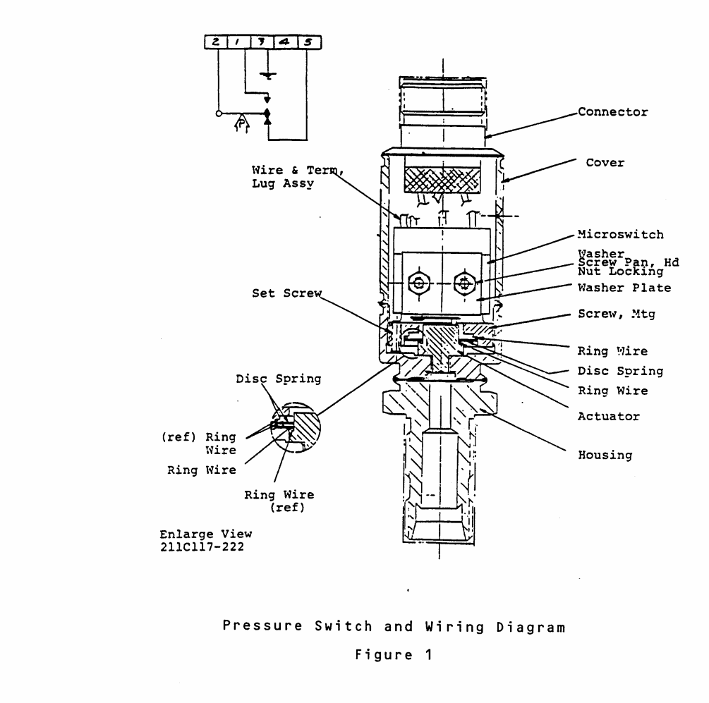
A.Description(See Figure 1)
说明(见图 1)
(1) The Eaton/PSD Pressure Switch Assemblies,PN’s 211C117-22 and 223 use a single diaphragm type pressure sensing element,a snap action spring system,a snap actionhermetic type electrical switch and a housing with the required pressure port and electrical connector.
Eaton/PSD 压力开关组件(PN’s 211C117-22 和 223)使用单膜片式压力传感元件、快动弹簧系统、快动密封式电气开关和带有所需压力端口和电气连接器的外壳。
(2) The pressure sensing diaphragm is anassembly of a thin sheet of stainless steel sandwiched between the pressure port fittingand the housing. These three components areheli-arc welded around their circumference.
压力传感膜片由不锈钢薄片组成,裹在压力端口接头和外壳之间。这三个组件的圆周均采用热弧焊接。
(3) The electrical switch is mounted to a threaded mounting screw with two machinescrews,Locking nuts and washers. These setscrews maintain the final switch mounting screw Location.
电气开关用两个机械螺钉、锁紧螺母和垫圈安装在螺纹安装螺钉上。 这些固定螺钉可保持开关安装螺钉的最终位置。
(4) After unit calibration,the electrical switch position is adjusted to insure operation within the snap stroke of the actuator.The two machine screws with locking nuts maintain the electrical switch in position with respect to the actuator travel.
部件校准后,调整电气开关的位置,以确保在作动器的快动行程内运行。两个带锁紧螺母的机加工螺钉将电气开关保持在与作动器行程相关的位置。
(5) The Housing and diaphragm back-up plate from one integral piece.The internal thread provides accurate switch setting.Three holes in the cover provide a gauge pressure reference.
外壳和膜片支撑板为一体,内螺纹提供精确的开关设置,盖板上的三个孔提供表压参考。
(6) The electrical connector with a stainlesssteel shell is heli-arc weLded to the cover.The cover is welded to the housing,thereby providing a structurally rigid assembly.
带有不锈钢外壳的电气连接器通过螺旋弧焊焊接到盖子上。盖子焊接在外壳上,从而提供了一个结构坚固的组件。
B. Operation
操作
(1) At zero gauge pressure the diaphragm is held down mechanically by the snap spring acting on the actuator to provide a clearance between the button and the housing.When pressure applied at the fLuid port reaches the actuation pressure the snap spring snaps through permitting pressure to instantaneously move the diaphragm,button,and actuator upward to actuate the electrical switch.
在压力表压力为零时,膜片通过作用在作动器上的卡簧以机械方式被压住,从而在按钮和外壳之间形成间隙。当流体端口施加的压力达到做东压力时,卡簧卡住,使压力瞬间将膜片、按钮和作动器向上移动,从而作动电气开关。
(2) The button having moved through its above mentioned clearance,now acts as a stop thereby preventing damage to the electrical switch during further pressure rise.
按钮通过上述间隙后,现在起到了止动作用,从而防止在压力进一步升高时损坏电气开关。
(3) With decreasing pressure and the snap action behavior(negative spring rate)of the snap spring,the diaphragm-button assembly is forced back to its start position at the deactuation pressure.
随着压力的减小和卡簧的弹力作用(负弹力),膜片-按钮组件在停用压力下被迫回到起始位置。
八、工作参数

九、在飞机系统中的工作原理及其互联
ENGINE BLEED AIR PRESSURE INDICATING SYSTEM – DESCRIPTION AND OPERATION
发动机引气压力显示系统 – 说明和操作
1. General
概述
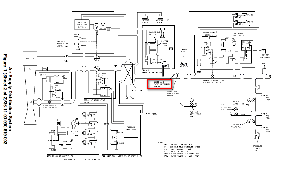
A. The pressure in the pneumatic manifold is sensed by two duct pressure transmitters. Pressure signals from the transmitters are sent to the the CMCS and EICAS via the ASCTU. The display of system pressure is shown on the main EICAS display, ECS synoptic page and on the ECS maintenance page.
气动歧管中的压力由两个管道压力传感器感测。传感器发出的压力信号通过 ASCTU 发送到 CMCS 和 EICAS。 系统压力显示在 EICAS 主显示屏、ECS 概览页面和 ECS 维护页面上。
B. The overpressure switch provides system fault indication on EICAS during an overpressure condition. A signal is sent to the ASCTU logic circuits to illuminate the SYS FAULT light and generate a BLEED 1, 2, 3 or 4 EICAS advisory message along with its associated BLEED OVPRESS 1, 2, 3 or 4 EICAS status message.
超压开关在超压情况下提供 EICAS 系统故障指示。 信号被发送到 ASCTU 逻辑电路,以点亮 SYS FAULT 指示灯,并生成 BLEED 1、2、3 或 4 EICAS 警报信息及其相关的 BLEED OVPRESS 1、2、3 或 4 EICAS 状态信息。
C. The bleed air pressure sensor continuously monitors the engine duct pressure downstream of the precooler and provides information to the CMCS.
引气压力传感器持续监控预冷却器下游的发动机管道压力,并向 CMCS 提供信息。
Bleed Air Overpressure Switch
引气超压开关
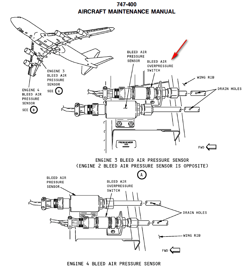
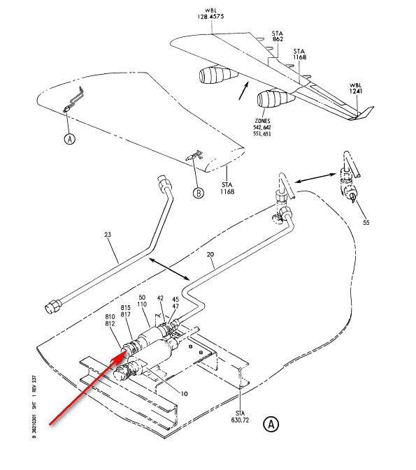
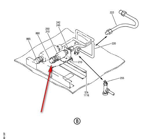
A. There are four bleed air overpressure switches installed in the wing leading edge. Access to the overpressure switch is through a panel on the wing leading edge inboard of the engine strut. The overpressure switch is located next to the pressure sensor.
机翼前缘安装有四个引气超压开关。 超压开关可通过发动机支柱内侧机翼前缘上的面板接近。 超压开关位于压力传感器旁边。
B. The bleed air overpressure switch is connected by a pneumatic sense line to a fitting at the precooler outlet. It senses the engine duct pressure for overpressure condition.
引气超压开关通过气动感应管路与预冷却器出口的接头相连。 它可感应发动机管道压力,以确定是否存在超压情况。
(1) When the bleed air pressure goes above 78-80 psig, the overpressure switch opens. If the switch stays open for more than 65 seconds an input is sent to the ASCTU logic circuits. A “SYS FAULT” light will come on and a BLEED 1, 2, 3 or 4 EICAS advisory message will come into view on EICAS along with its associated BLEED OVPRESS 1, 2, 3 or 4 EICAS status message, when the ECS status display is selected.
当引气压力超过 78-80 psig 时,超压开关打开。 如果开关打开时间超过 65 秒,则会向 ASCTU 逻辑电路发送一个输入信号。 当选择 ECS 状态显示时,”SYS FAULT(系统故障)”指示灯将亮起,EICAS 上将显示 BLEED 1、2、3 或 4 EICAS 警报信息以及相关的 BLEED OVPRESS 1、2、3 或 4 EICAS 状态信息。
Bleed Air Pressure Indication and Monitoring System
引气压力指示和监测系统
A. The BITE logic continuously monitors the bleed pressure sensor for high or low engine manifold pressure; and also monitors the integrity of the overpressure switch.
BITE 逻辑系统持续监控引气压力传感器,以确定发动机歧管压力是否过高或过低;同时还监控超压开关的完整性。
B. External air pressure source indication is shown by an EXT AIR message on the EICAS ECS synoptic page when ground air is available to pack 1, pack 2, or pack 3.
当 pack 1 ,2 或 3 可以使用地面空气时,EICAS ECS 概览页面上的 EXT AIR 信息会显示外部气压源指示。