A330-200/300
TECHNICAL TRAINING MANUAL
ICE AND RAIN PROTECTION
技术培训手册
防冰防雨
CONTENTS 目录
ICE AND RAIN PROTECTION
Ice & Rain Protection Line MAINT Briefing (2)
防冰和防雨系统航线维护
WING ICE PROTECTION
Wing Ice Protection D/O (3)
机翼防冰
ENGINE AIR INTAKE ICE PROTECTION
Engine Air Intake Ice Protection D/O (3)
发动机进气道防冰
PROBE ICE PROTECTION
Probe Ice Protection D/O (3)
探头防冰
WINDSHIELD PROTECTION
Windshield A.ICE/Defogging & Rain PROT D/O (3)
风挡防冰和除雾
POTABLE AND WASTE WATER ICE PROTECTION
Potable & Waste Water Ice Protection D/O (3)
饮用水/废水防冰
ESCAPE SLIDE LOCKING MECHANISM ICE PROTECTION
Escape SLD Locking Mechanism Ice PROT D/O (3)
逃生SLD锁定机构防冰
ICE DETECTION
Ice Detection D/O (3)
冰探测
MAINTENANCE PRACTICE
Ice & Rain Protection System Base Maintenance(3)
防冰和防雨系统基础维护
ICE & RAIN PROTECTION LINE MAINT BRIEFING (2)
SYSTEM OVERVIEW
系统概述
GENERAL
概述
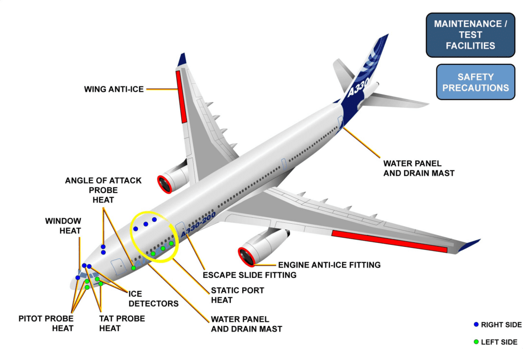
The Ice and Rain Protection System lets the aircraft operate without restriction in icing conditions or heavy rain. Hot air or electrical heating protects critical areas of the aircraft. The different sub systems of the Ice and Rain Protection System are:
防冰防雨系统可使飞机在结冰或大雨条件下不受任何限制地运行。热空气或电加热可保护飞机的关键部位。防冰防雨系统的不同子系统包括:
– wing ice protection,
– 机翼防冰
– engine air intake ice protection,
– 发动机进气口防冰
– probe ice protection,
– 探头防冰
– windshield anti-icing, defogging and rain protection,
– 挡风玻璃防冰、除雾和防雨、
– potable and waste water ice protection,
– 饮用水和废水防冰、
– escape slide locking mechanism ice protection,
– 逃生滑梯锁定装置防冰、
– ice detection,
– 冰探测、
– maintenance/test facilities.
– 维护/测试设备。
When you work on aircraft, you must obey all the safety procedures listed in the AMM.
在飞机上工作时,必须遵守 AMM 中列出的所有安全程序。
ICE & RAIN PROTECTION LINE MAINT BRIEFING (2)
SYSTEM OVERVIEW (continued)
WING ICE PROTECTION
机翼防冰
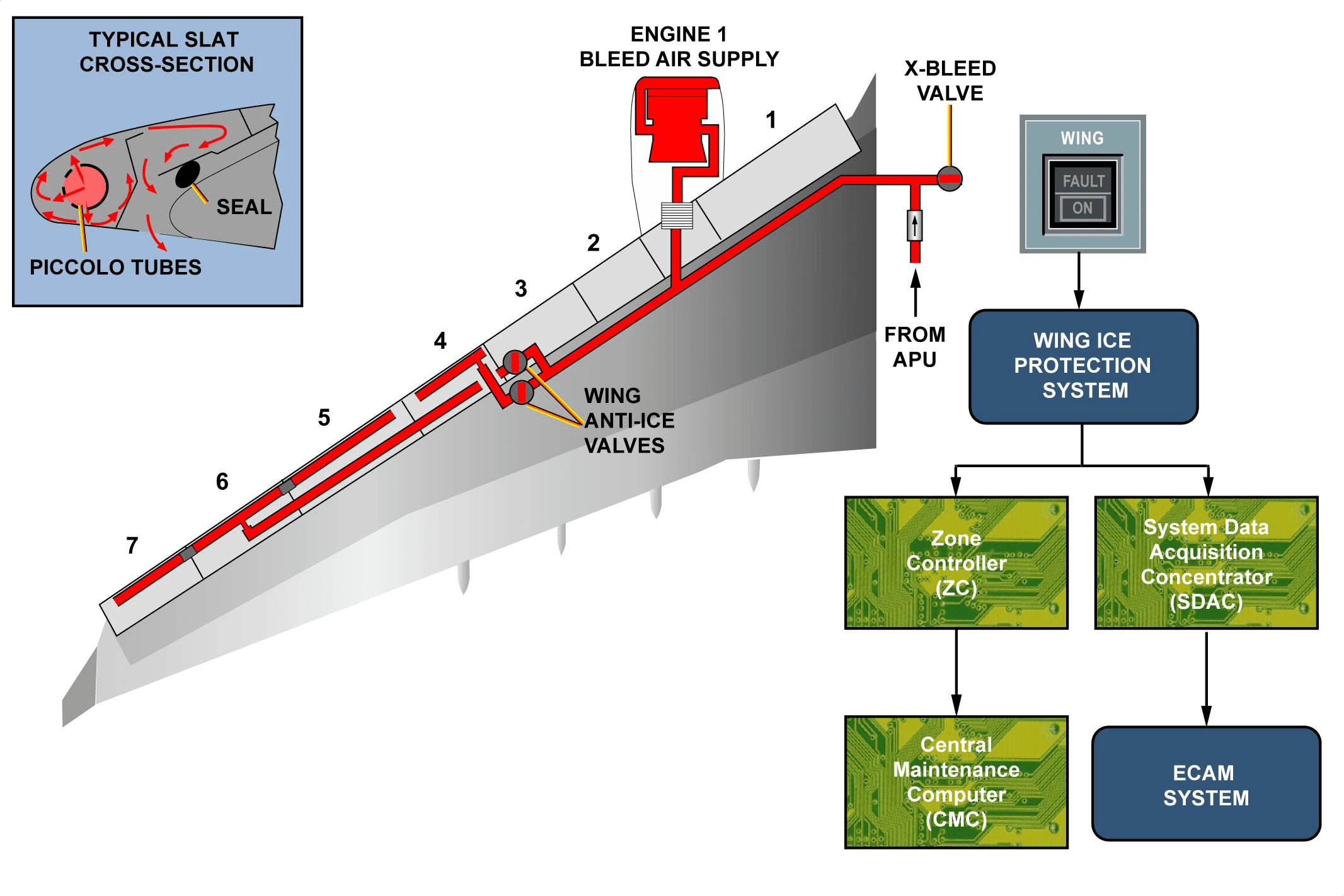
During icing conditions, hot air is supplied by the pneumatic system to the four outboard slats to raise the temperature. Bleed air is supplied to each wing through two Wing Anti Ice (WAI) valves, one for the slat number four and one for slats number five, six and seven.
在结冰条件下,气动系统向四个外侧缝翼提供热空气,以提高温度。引气通过两个机翼防冰(WAI)活门供应给每个机翼,一个用于四号缝翼,另一个用于五、六和七号缝翼。
If a failure occurs in the wing ice protection system:
如果机翼防冰系统发生故障:
– the Zone Controller (ZC) sends the failure data to the Centralized Maintenance Computer (CMC),
– 区域控制器 (ZC) 将故障数据发送到中央维护计算机 (CMC)、
– the System Data Acquisition Concentrator (SDAC) sends data to the ECAM.
– 系统数据采集集中器 (SDAC) 将数据发送至 ECAM。
ICE & RAIN PROTECTION LINE MAINT BRIEFING (2)
SYSTEM OVERVIEW (continued)
ENGINE AIR INTAKE ICE PROTECTION
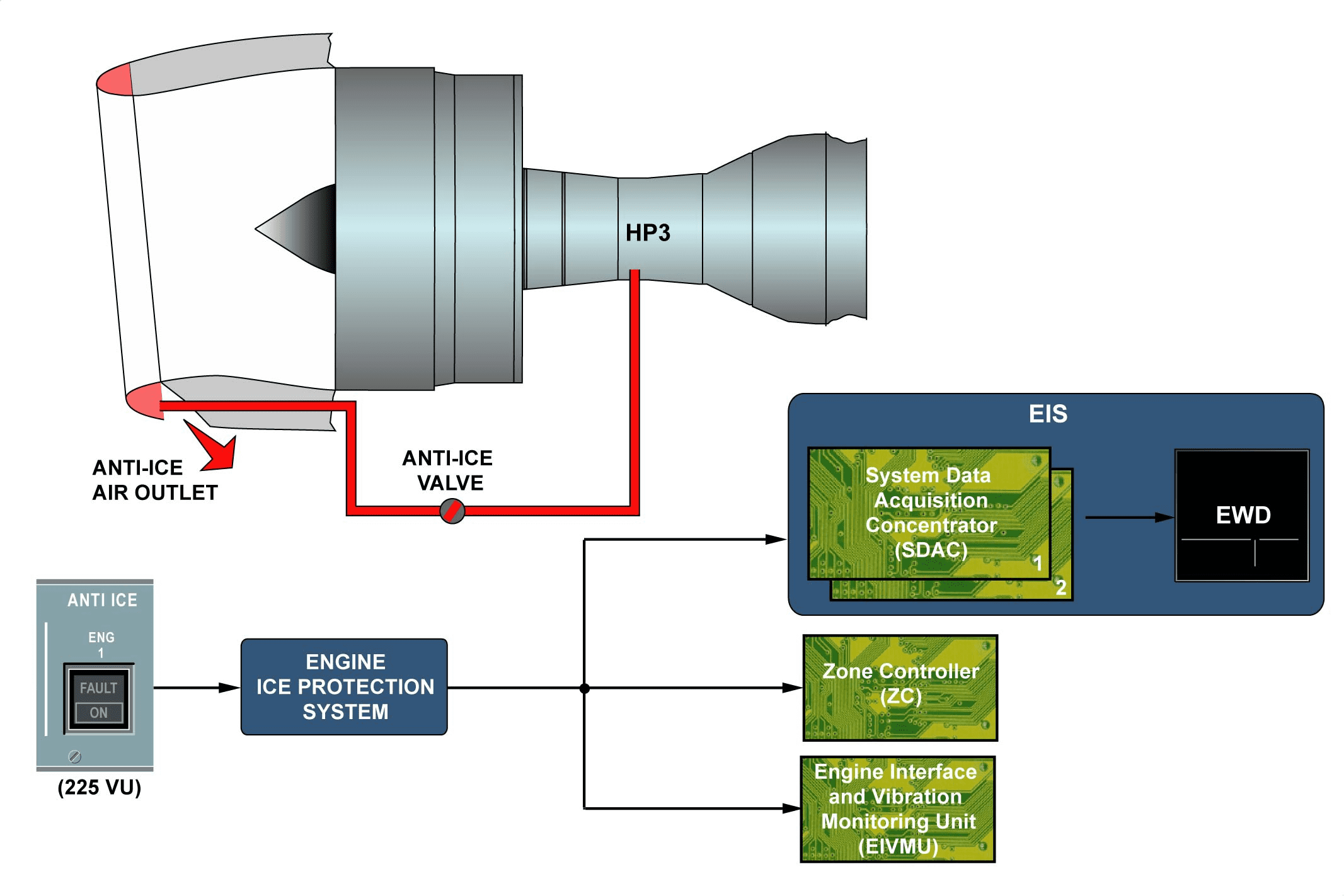
Engine air intake ice protection protects the engine during operation in ambient icing or snowy conditions. Hot air bled from high pressure compressor third stage is used to heat the air intake lip. Hot air is supplied through an engine air intake anti-ice valve.
发动机进气口防冰
发动机进气防冰可在环境结冰或积雪条件下保护发动机。高压压缩机第三级引气中的热气用于加热进气唇。热空气通过发动机进气防冰活门供应。
The engine air intake ice protection system interfaces with the SDAC for the ECAM system for fault indication, the Zone Controller (ZC) and the Engine Interface Vibration Monitoring Unit (EIVMU) for engine control.
发动机进气防冰系统与用于故障指示的 ECAM 系统的 SDAC、区域控制器 (ZC) 和用于发动机控制的发动机界面振动监控装置 (EIVMU) 相连接。
ICE & RAIN PROTECTION LINE MAINT BRIEFING (2)
SYSTEM OVERVIEW (continued)
PROBE ICE DETECTION
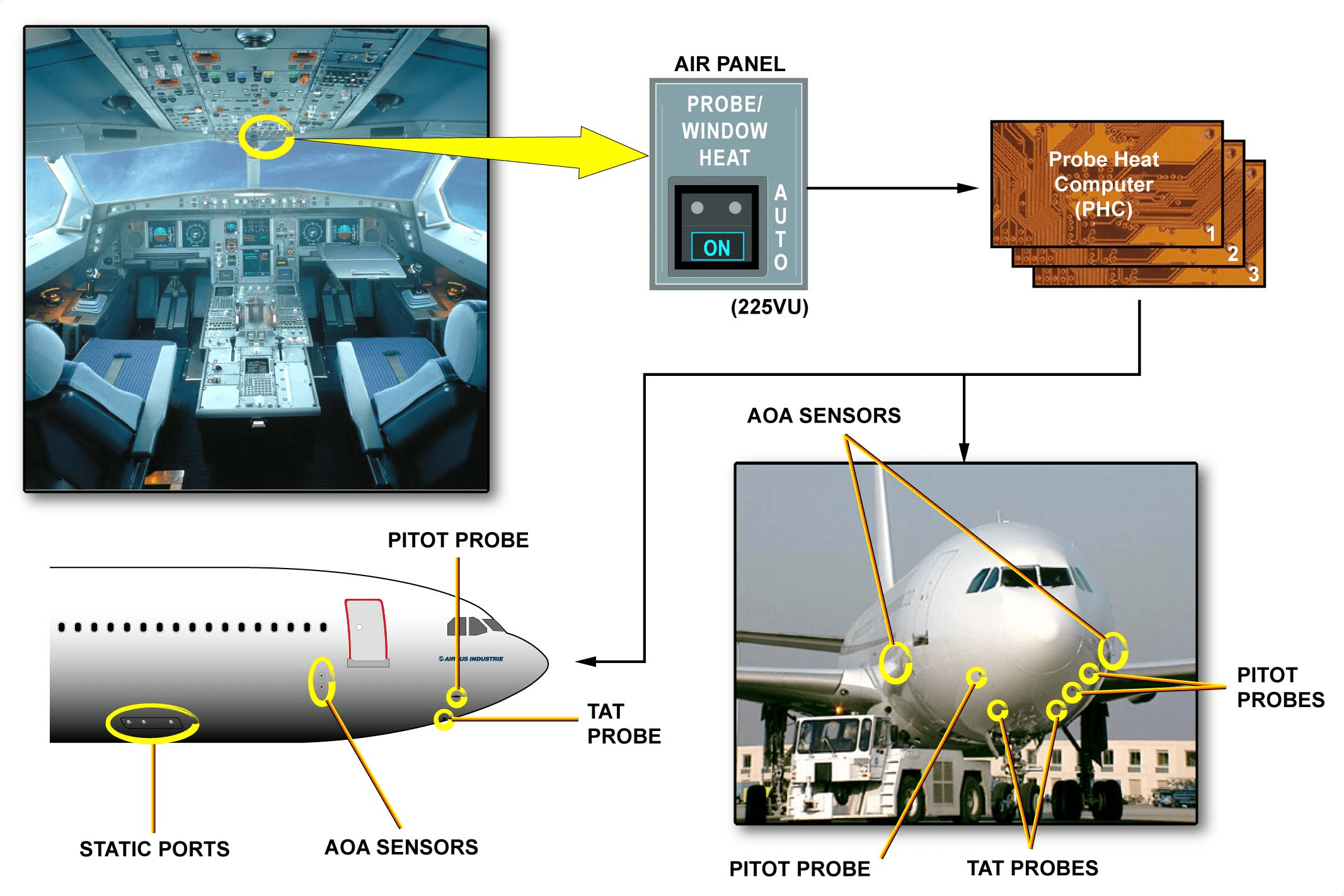
Ice protection of the static ports, Angle Of Attack (AOA) sensors, pitot and Total Air Temperature (TAT) probes is achieved by electrical heating. Three Probe Heat Computers (PHCs) control the heating elements. Probe heating system is automatically or manually controlled. In case of severe icing conditions on ground, automatic operation can be overridden with the PROBE/WINDOW HEAT P/BSW.
探头结冰检测
静态端口、仰角 (AOA) 传感器、皮托管和总温 (TAT) 探头的防冰是通过电加热实现的。三个探头加热计算机(PHC)控制加热元件。探头加热系统可自动或手动控制。在地面严重结冰的情况下,可通过PROBE/WINDOW HEAT P/BSW 超控自动操作。
ICE & RAIN PROTECTION LINE MAINT BRIEFING (2)
SYSTEM OVERVIEW (continued)
WINDSHIELD ANTI-ICING
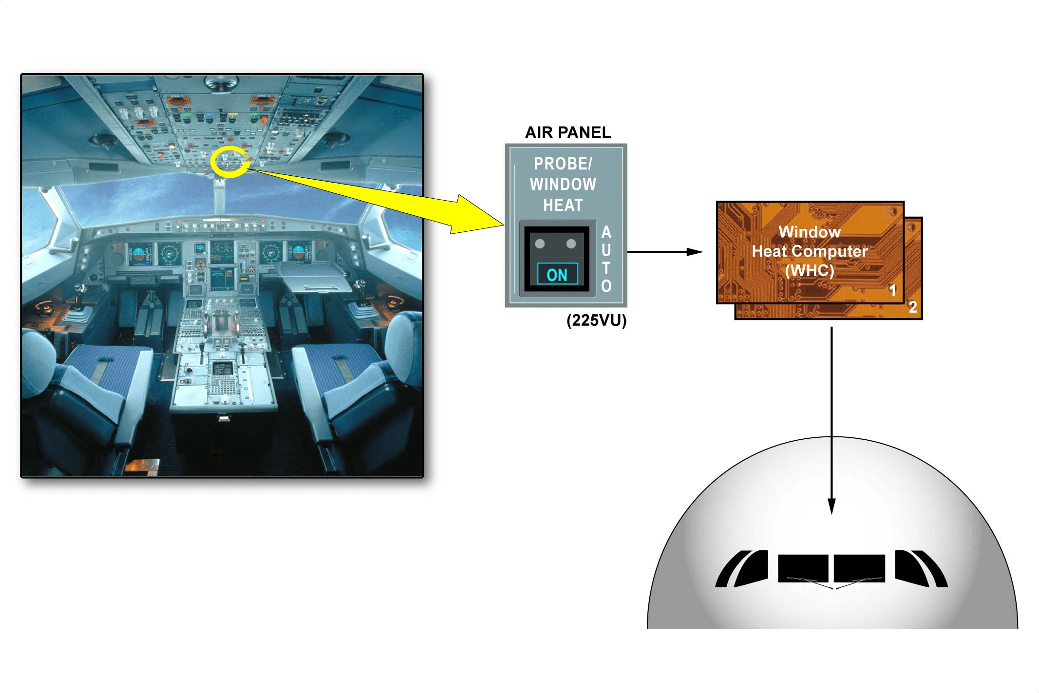
Ice protection for windshield and demisting for windows is electrically achieved. Two independent Window Heat Computers (WHCs), one for each side, monitor and control the heaters. They include an overheat protection. Window heating system is automatically or manually controlled. In case of severe icing conditions on ground, automatic operation can be overridden with the PROBE/WINDOW HEAT P/BSW.
挡风玻璃防冰
挡风玻璃防冰和窗户除雾是通过电动方式实现的。两个独立的窗户加热计算机(WHC)分别监控两侧的加热器。它们包括过热保护装置。窗户加热系统可自动或手动控制。在地面严重结冰的情况下,可通过PROBE/WINDOW HEAT P/BSW 来超控自动操作。
ICE & RAIN PROTECTION LINE MAINT BRIEFING (2)
SYSTEM OVERVIEW (continued)
RAIN PROTECTION
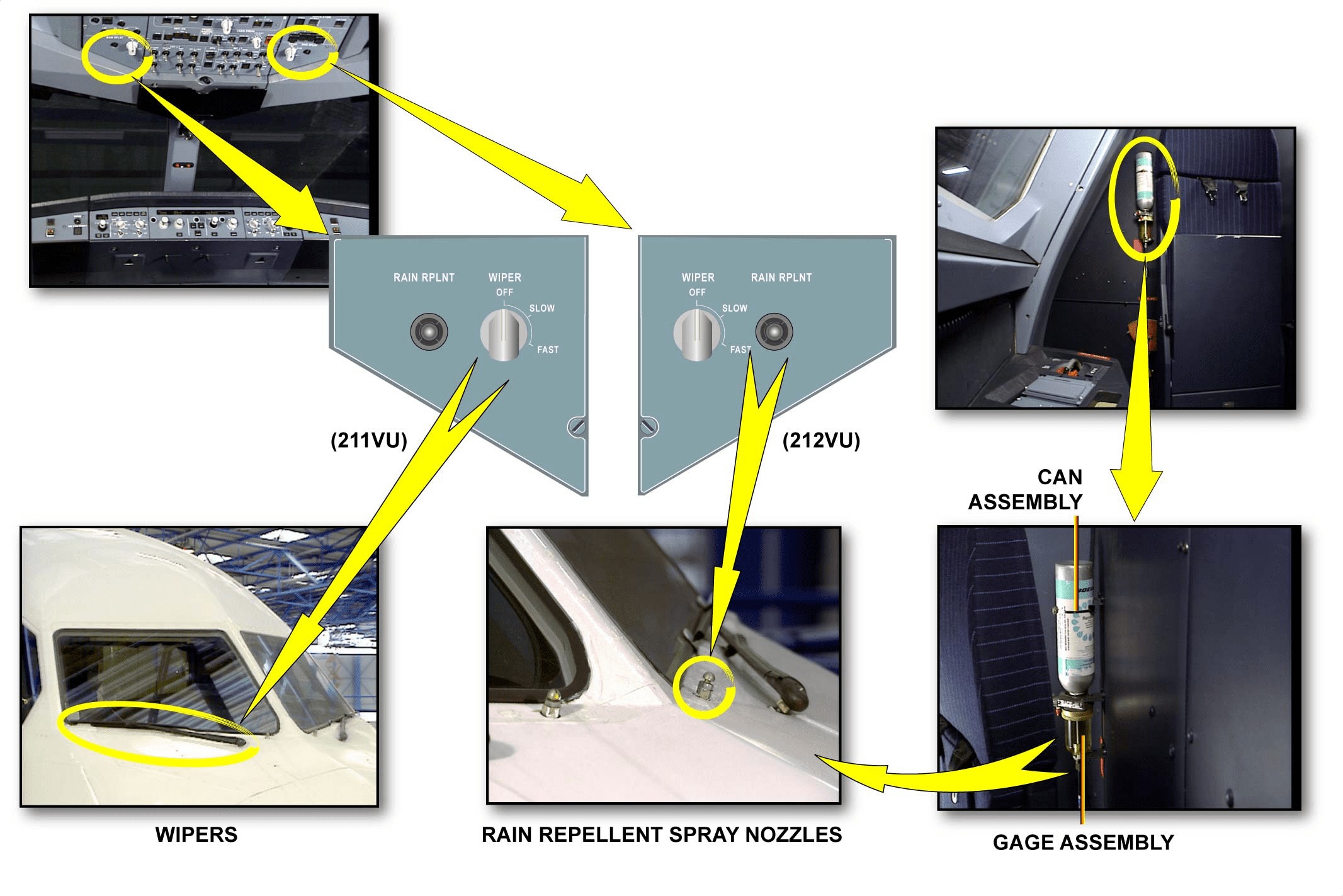
Rain removal from the windshield is done by two independent wipers and in heavy rain, by a rain repellent system. These systems are controlled from the overhead panel. The rain repellent is discharged onto the left or right windshield from a pressurized canister installed at the rear of the cockpit.
防雨
挡风玻璃上的雨水由两个独立的雨刷清除,大雨时则由防雨系统清除。这些系统由顶部面板控制。防雨剂从安装在驾驶舱后部的一个加压罐排放到左侧或右侧挡风玻璃上。
ICE & RAIN PROTECTION LINE MAINT BRIEFING (2)
SYSTEM OVERVIEW (continued)
POTABLE AND WASTE WATER ICE PROTECTION
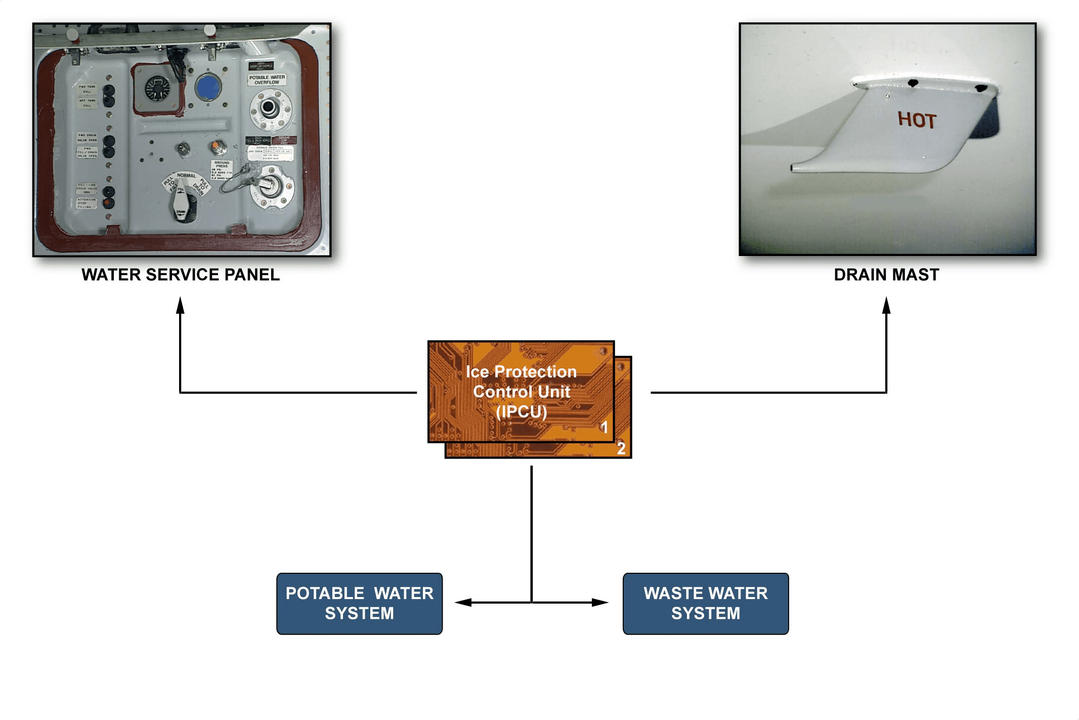
An automatic ice protection of the water lines is installed to prevent ice formation. The system has 3 subsystems:
– potable water ice protection,
– waste water ice protection,
– water servicing panels heating.
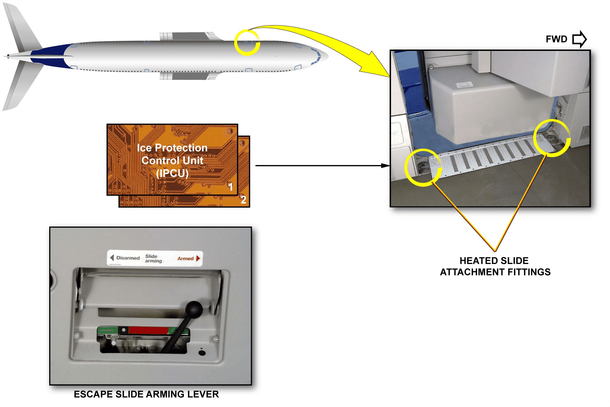
Two Ice Protection Control Units (IPCUs) control the electrical heating elements in the related area.
饮用水和废水防冰
水管安装了自动防冰装置,以防止结冰。该系统有 3 个子系统:
– 饮用水防冰、
– 废水防冰、
– 勤务板加热。
两个防冰控制单元(IPCU)控制相关区域的电加热元件。
ICE & RAIN PROTECTION LINE MAINT BRIEFING (2)
SYSTEM OVERVIEW (continued)
ESCAPE SLIDE LOCKING MECHANISM ICE PROTECTION
An electrical ice protection system is installed to let a safe disarming of the escape slides on ground. The system prevents ice formation from water condensation in the Slide Attachment Fittings (SAFs).
Each passenger/crew door has two heated SAFs. The heating elements located in the related locking plate are powered automatically when icing conditions are detected, if the escape slide is armed. Two IPCUs control the heating elements.
逃生滑梯锁定装置防冰
安装有电气防冰系统,可在地面上安全解除逃生滑梯。该系统可防止水在滑梯连接装置(SAF)中凝结成冰。
每个乘客/机组人员舱门都有两个可加热的SAF。当检测到结冰情况时,如果逃生滑梯已就位,位于相关锁定板内的加热元件会自动供电。两个 IPCU 控制加热元件。
ICE & RAIN PROTECTION LINE MAINT BRIEFING (2)
SYSTEM OVERVIEW (continued)
ICE DETECTION
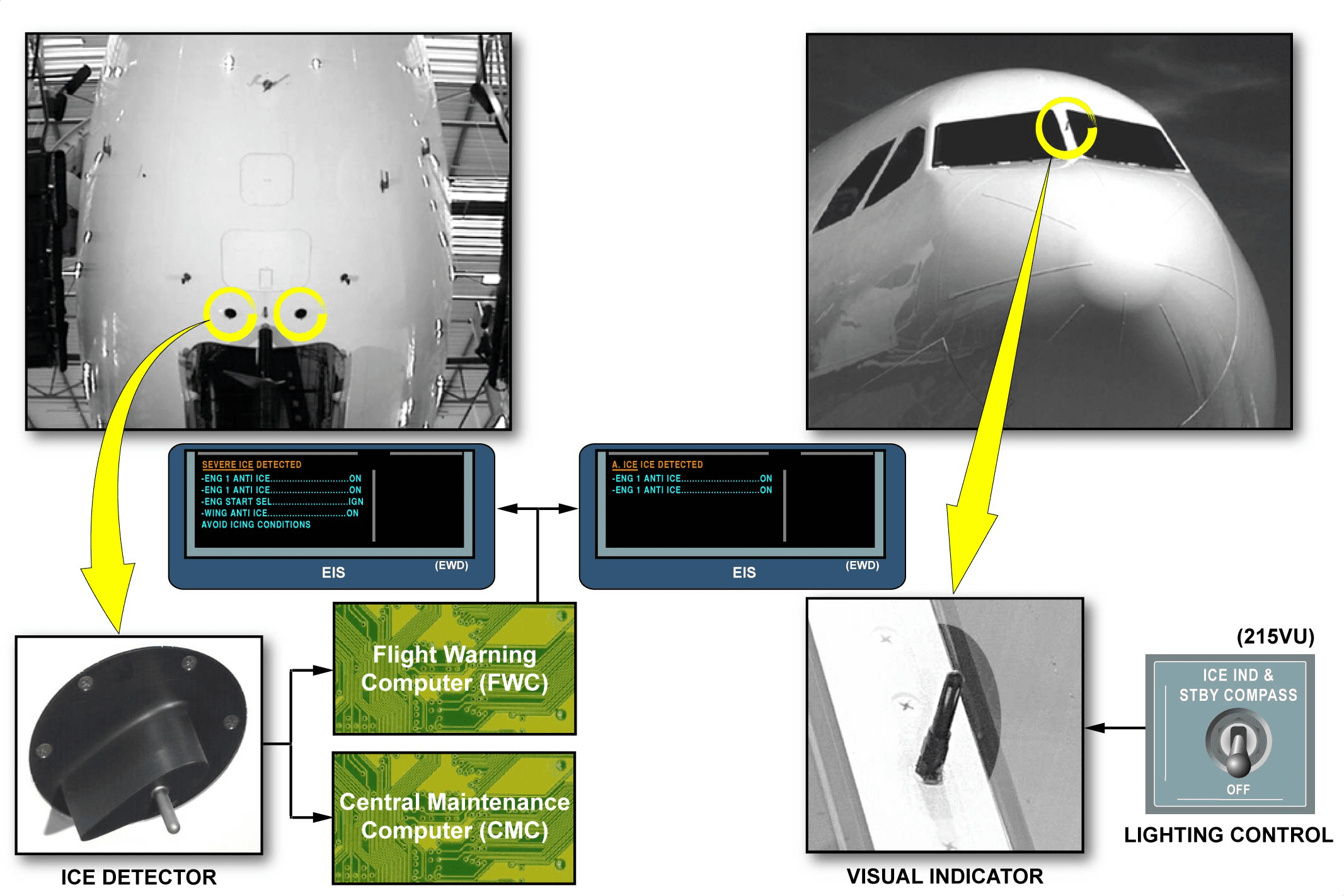
The function of the ice detection system is to give the crew a better detection of the icing conditions. The system has two separate ice detectors located on the forward lower section of the fuselage. An external visual ice indicator with an integrated light is installed between the two windshields.
结冰探测
结冰探测系统的功能是让机组人员更好地探测结冰情况。该系统有两个独立的冰探测仪,位于机身的前下部。在两块挡风玻璃之间安装了一个带集成照明灯的外部可视结冰指示器。
ICE & RAIN PROTECTION LINE MAINT BRIEFING (2)
SERVICING
勤务
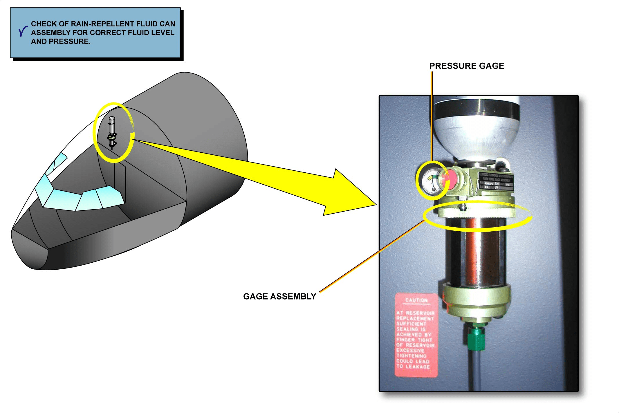
CHECK OF RAIN-REPELLENT FLUID CAN ASSEMBLY FOR CORRECT FLUID LEVEL AND PRESSURE
This task is accomplished to check that the rain-repellent fluid level and pressure are set correctly.
For the pressure gage:
– make sure that the pointer points to the green area,
– if the pointer points to the yellow area, replace the rain-repellent fluid can.
For the fluid level:
– make sure that there is sufficient rain-repellent fluid in the gage assembly,
– if you see the surface of the fluid, replace the rain-repellent fluid can,
– if level and/or pressure is/are not correct, change the rain-repellent fluid can.
检查防雨液罐组件液位和压力是否正确
完成此任务的目的是检查防雨剂的液位和压力是否设置正确。
对于压力表:
– 确保指针指向绿色区域、
– 如果指针指向黄色区域,则更换防雨剂罐。
对于液位:
– 确保压力表组件中有足够的防雨剂、
– 如果看到液体表面,则更换防雨剂罐、
– 如果液位和/或压力不正确,则更换防雨剂罐。
ICE & RAIN PROTECTION LINE MAINT BRIEFING (2)
SERVICING (continued)
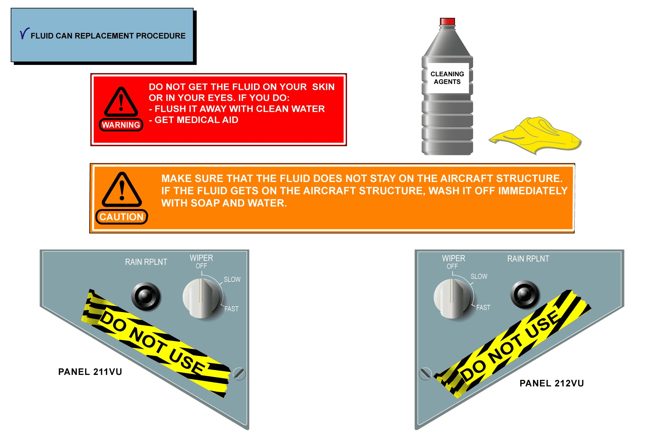
FLUID CAN REPLACEMENT PROCEDURE 更换液体罐程序
WARNING: DO NOT GET THE FLUID ON YOUR SKIN OR IN YOUR EYES. IF YOU DO:
– FLUSH IT AWAY WITH CLEAN WATER
– GET MEDICAL AID.
警告:不要将液体弄到皮肤上或眼睛里。如果这样了:
– 用清水冲洗干净
– 寻求医疗救助。
CAUTION: MAKE SURE THAT THE FLUID DOES NOT STAY ON THE AIRCRAFT STRUCTURE. IF THE FLUID GETS ON THE AIRCRAFT STRUCTURE, WASH IT OFF IMMEDIATELY WITH SOAP AND WATER.
注意:确保液体不会留在飞机结构上。如果液体沾到飞机结构上,请立即用肥皂和水冲洗。
Put a warning notice in the cockpit to tell people not to operate the RAIN RePeLeNT P/BSWs.
在驾驶舱内张贴警告提示,告知乘客不要操作 RAIN RePeLeNT P/BSW。
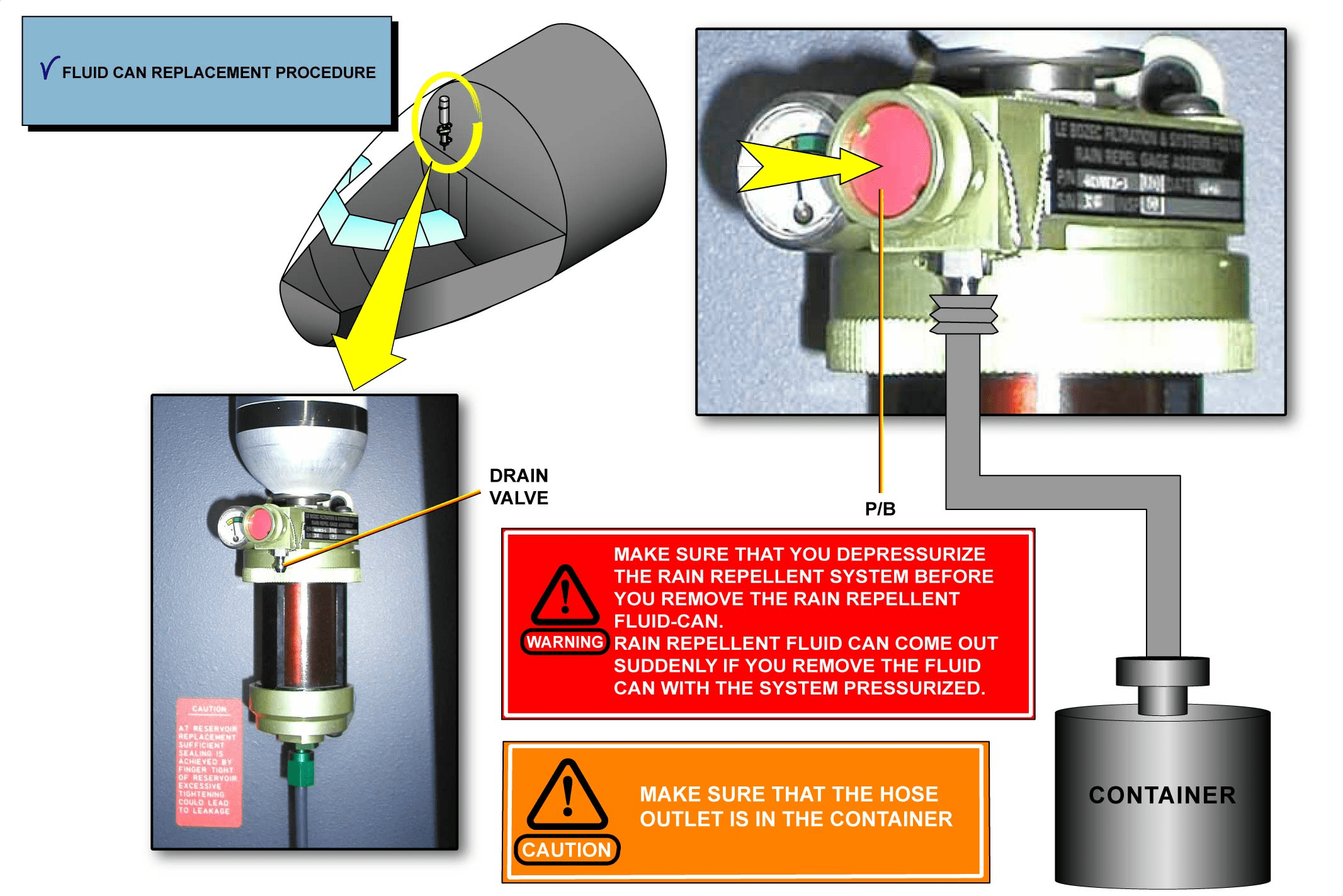
WARNING: MAKE SURE THAT YOU DEPRESSURIZE THE RAIN REPELLENT SYSTEM BEFORE YOU REMOVE THE RAIN REPELLENT FLUID CAN. RAIN REPELLENT FLUID CAN COME OUT SUDDENLY IF YOU REMOVE THE FLUID CAN WITH THE SYSTEM PRESSURIZED.
警告:在拆卸防雨剂罐之前,请确保对防雨系统进行减压。如果在系统加压的情况下取下液体罐,防雨剂液体会突然流出。
Connect a hose to the drain valve of the rain repellent fluid gage and put the hose outlet in a container.
Push the P/B to depressurize the system.
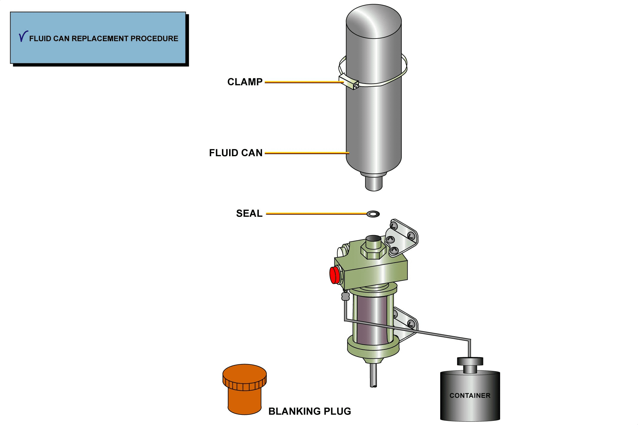
– remove the clamp,
– loosen and remove the fluid can,
– remove and discard the seal,
– put a blanking plug on the disconnected line ends,
– after cleaning the components interfaces, remove the blanking plug and install a new seal,
– put the new rain repellent fluid can and tighten it manually,
– install the clamp on the can and tighten it,
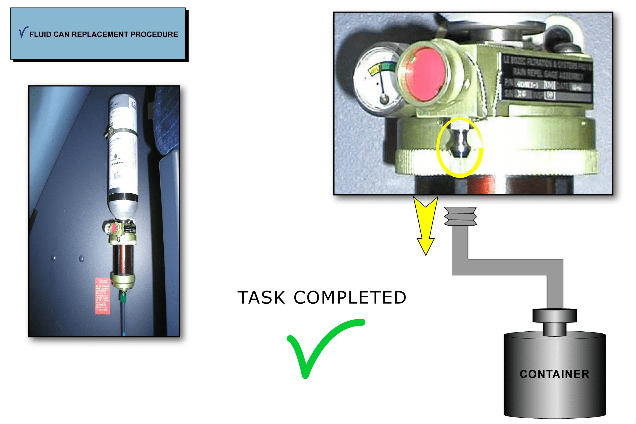
– push the P/B,
– make sure that the fluid level is correct and increases to the correct pressure,
– make sure that there is no leak.
– disconnect the hose from the drain valve,
– remove the container from the A/C,
– make sure that the work area is clean,
– clear of tools and items,
– close the access door,
– remove the warning notice from the cockpit.
将软管连接到防雨剂表的排放阀上,并将软管出口放入容器中。
按下 P/B 给系统减压。
– 拆卸管夹、
– 松开并拆除液体罐、
– 取下并报废密封件、
– 在断开的管路末端装上封堵塞、
– 清洁部件接口后,取下封堵塞并安装新密封件、
– 装上新的防雨液罐并手动拧紧、
– 在罐子上安装管夹并拧紧、
– 按下 P/B、
– 确保油位正确并增加到正确的压力、
– 确保没有泄漏。
– 断开排放阀上的软管、
– 从飞机上取出容器、
– 确保工作区域清洁、
– 清除工具和物品、
– 关闭接近门、
– 取下驾驶舱内的警告提示。
This Page Intentionally Left Blank
ICE & RAIN PROTECTION LINE MAINT BRIEFING (2)
MEL/DEACTIVATION
MEL/停用
DEACTIVATION OF THE WING ANTI-ICE CONTROL VALVE IN THE CLOSED LOCKED POSITION
The A/C Minimum Equipment List (MEL) will allow dispatch with one or more wing anti-ice valve in the locked closed position or with one open on each side. Let us see the valve deactivation in closed position provided the A/C is not operated in icing conditions:
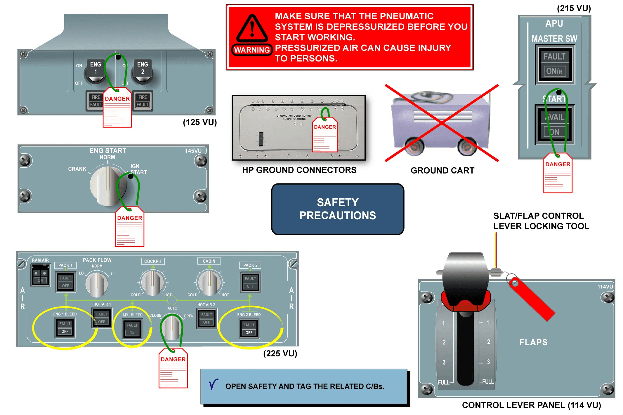
– check that the pneumatic system is not pressurized, the engines and the APU are shut down,
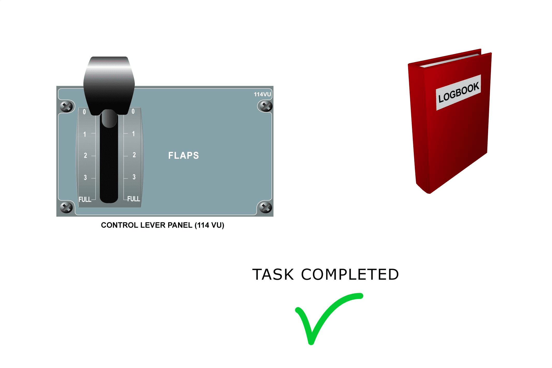
– use the slat/flap control lever-locking tool to lock the slat/flap control lever in position,
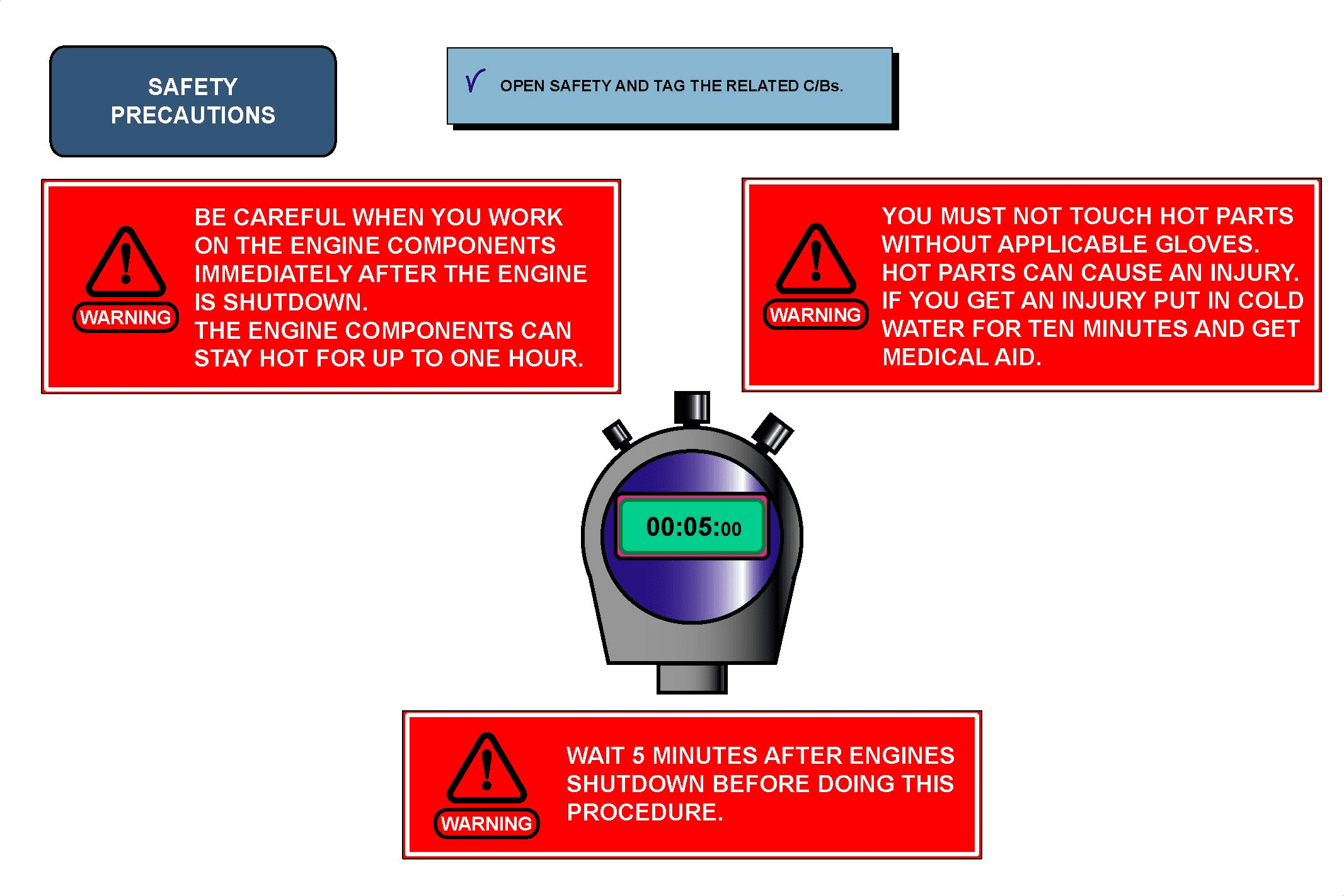
– open, safety and tag the related circuit breakers.
在关闭锁定位置停用机翼防冰活门位置
飞机最低设备清单(MEL)允许在一个或多个机翼防冰活门处于锁定关闭位置或两侧各打开一个的情况下进行放行。让我们看看飞机不在结冰条件下运行的情况下,活门在关闭位置的停用情况:
– 检查气动系统未加压,发动机和 APU 关闭、
– 使用缝翼/副翼控制杆锁定工具将缝翼/副翼控制杆锁定在位、
– 打开相关的断路器,确保安全并贴上标签。
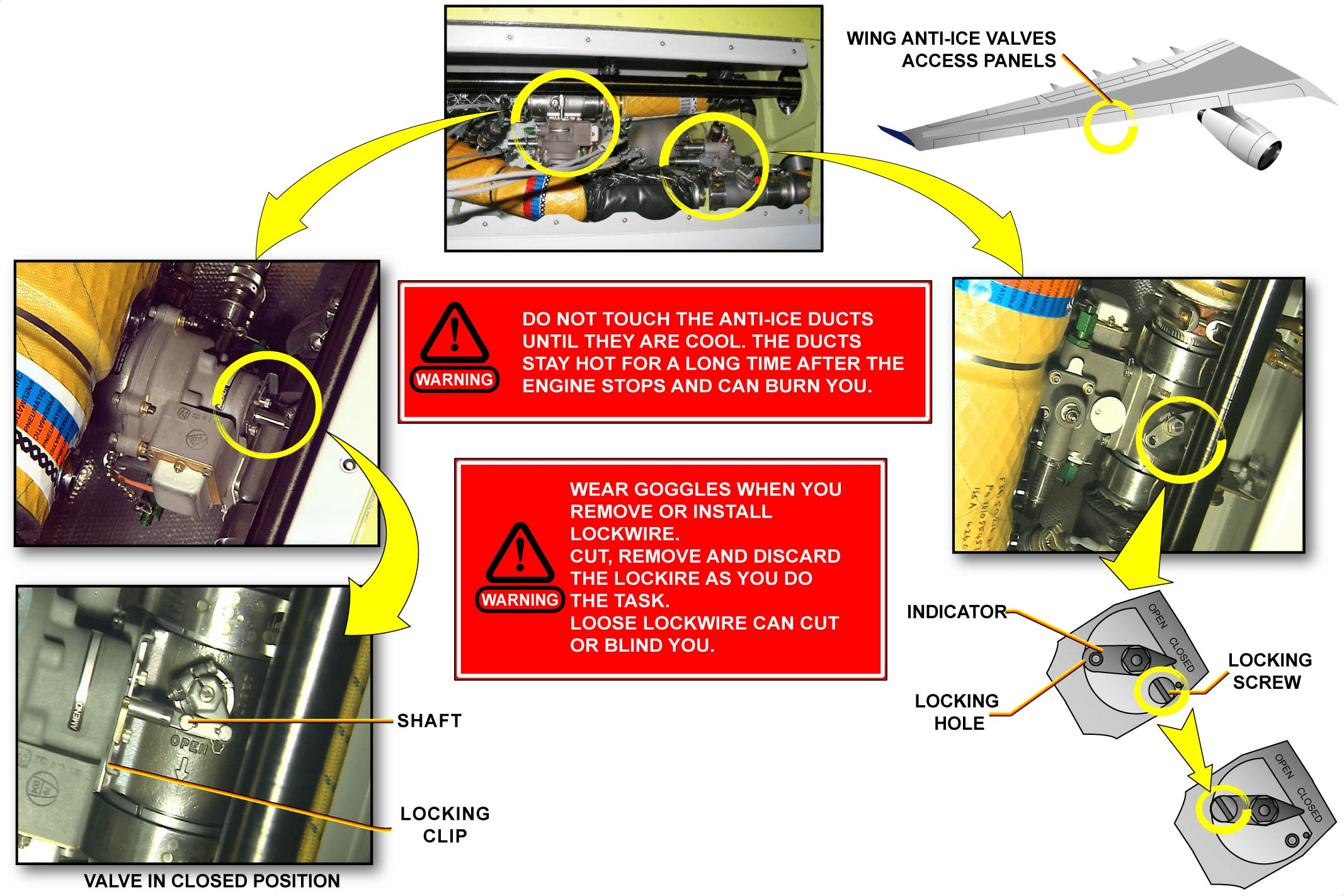
WARNING: DO NOT TOUCH THE ANTI-ICE DUCTS UNTIL THEY ARE COOL. THE DUCTS STAY HOT FOR SOME TIME AFTER THE ENGINE STOPS AND CAN BURN YOU. WEAR GOOGLES WHEN YOU REMOVE OR INSTALL LOCKWIRE. CUT, REMOVE AND DISCARD THE LOCKWIRE AS YOU DO THE TASK. LOOSE LOCKWIRE CAN CUT OR BLIND YOU.
警告:在防冰管道冷却之前,请勿触摸。发动机停机后,防冰管道会在一段时间内保持高温,可能导致烫伤。拆卸或安装保险丝时请戴上护目镜。在执行任务时剪断、拆除并报废保险丝。松动的锁线可能会割伤或弄瞎您的眼睛。
To gain access to the valves:
– remove the applicable access panel.
要接近活门:
– 拆下相应的接近面板。
The wing anti-ice valves are identical but the locking procedure is different due to the valve installation position. A lock screw locks the wing valve below. A locking clip locks the wing valve above. For the wing anti-ice valve above, an inspection mirror is necessary.
机翼防冰活门是相同的,但由于活门的安装位置不同,锁定程序也不同。锁紧螺钉锁定下方的活门。锁夹锁定上方的活门。对于上方的机翼防冰阀,需要一个检查镜。
To deactivate the wing anti-ice control valve below:
– remove and discard the lockwire from the locking screw,
– move the indicator to the closed position,
– remove the locking screw from the stowage position,
– install the locking screw through the locking hole in the indicator,
– lockwire the locking screw in position.
要停用下方的机翼防冰控制活门,请执行以下操作
– 拆除和报废锁紧螺钉上的保险丝、
– 将指示器移至关闭位置、
– 将锁紧螺钉从存放位置取下、
– 穿过指示器上的锁定孔安装锁定螺钉、
– 对锁紧螺钉打上保险丝。
For the wing anti-ice valve above, the procedure is different:
– check that the indicator is in the closed position,
– if not, slowly move the shaft with your hand to the required position,
– move the locking clip across until you feel the lock engages,
– if possible, slightly adjust the position of the shaft to get a movement of the locking clip.
对于上述机翼防冰活门,程序有所不同:
– 检查指示器是否处于关闭位置、
– 如果不在,用手慢慢将轴移动到所需位置、
– 横向移动锁夹,直到感觉到锁扣啮合、
– 如果可能,稍微调整轴的位置,使锁夹移动。
NOTE: The unlocked position of the locking clip is in the middle-free position. It can be moved in either direction to lock the valve.
– remove the locking tool slat/flap control lever,
– check that tools used during this procedure are removed,
– install the applicable access panel.
NOTE: Make an entry in the A/C technical log after the wing anti-ice control valve has been deactivated in the closed locked position.
注意:锁夹的解锁位置为中间自由位置。可向任一方向移动以锁定活门。
– 取下锁定工具缝翼 / 副翼控制杆、
– 检查本程序中使用的工具是否已拆除、
– 安装适用的接近面板。
注意:在关闭锁定位置停用机翼防冰控制活门后,在飞机技术日志中进行记录。
ICE & RAIN PROTECTION LINE MAINT BRIEFING (2)
MEL/DEACTIVATION (continued)
DEACTIVATION OF THE ENG AIR-INTAKE A-ICE CTRL VALVE IN THE CLOSED LOCKED POSITION
The A/C MMEL will allow dispatch with one engine-air-intake anti-ice valve in the locked closed position or with one or both in open position. Let us see the valve deactivation in closed position provided the A/C is not operated in icing conditions.
在关闭锁定位置停用发动机进气防冰控制活门位置
在一个发动机进气防冰活门处于锁定关闭位置或一个或两个发动机进气防冰活门均处于打开位置的情况下,飞机MMEL允许放行。让我们看看关闭位置的活门停用情况,前提是飞机不在结冰条件下运行。
WARNING: BE CAREFUL WHEN YOU WORK ON THE ENGINE COMPONENTS IMMEDIATELY AFTER THE ENGINE IS SHUTDOWN. THE ENGINE COMPONENTS CAN STAY HOT FOR UP TO ONE HOUR. WAIT FIVE MINUTES AFTER ENGINES SHUTDOWN BEFORE DOING THIS PROCEDURE. YOU MUST NOT TOUCH HOT PARTS WITHOUT APPLICABLE GLOVES. HOT PARTS CAN CAUSE AN INJURY. IF YOU GET AN INJURY PUT IT IN COLD WATER FOR TEN MINUTES AND GET MEDICAL AID.
警告:在发动机关闭后立即对发动机部件进行操作时要小心。发动机部件的热量可持续一小时。在发动机关闭后等待五分钟再执行此程序。在没有戴手套的情况下,不得接触高温部件。高温零件可能会导致受伤。如果受伤,请将其放入冷水中浸泡十分钟,然后就医。
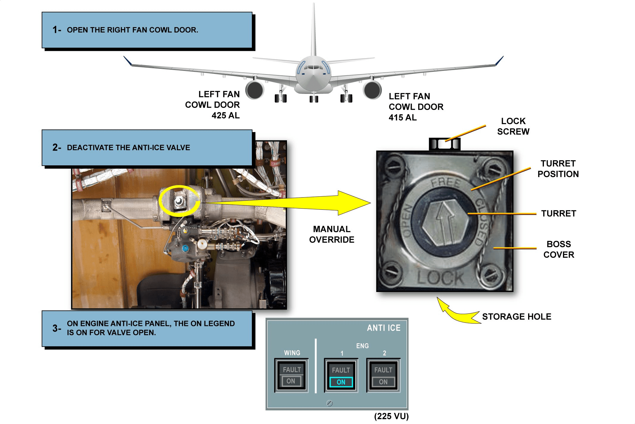
Open, safety and tag the related circuit breakers. Make sure that the engines shutdown occurred at least five minutes before you do this procedure:
– open the left fan cool door to gain access to the engine air-intake anti-ice valve,
– lock the anti-ice valve in the open or closed position,
NOTE: The arrow on the turret shows the relation of the butterfly valve to the valve body.
– remove the lockwire from the turret hole,
– remove the lock screw from the storage hole,
– use an applicable wrench on the turret and move the butterfly valve to the necessary position in the valve body (open or closed),
– hold the valve in the necessary position and install the lock screw through the boss cover and the turret,
– secure the turret with lockwire,
– make sure that the ANTI-ICE ENG 1(2) P/BSW is pushed (ON legend comes on),
NOTE: This test is required only in case the valve is deactivated in the OPEN position.
– check that tools used during this procedure are removed,
– close the left fan cowl door,
– put a warning notice in the cockpit to tell persons which anti-ice valve is locked in the open (or the closed) position
– make an entry in the A/C technical log that the engine air-intake anti-ice valve has been deactivated locked in the closed position.
打开相关断路器,确保其安全并贴上标签。在执行此程序之前,确保发动机至少停机五分钟:
– 打开左侧风扇冷却门,以进入发动机进气防冰活门、
– 将防冰活门锁定在打开或关闭位置、
注:转动指示器上的箭头表示蝶板与活门壳体的关系。
– 从转动指示器中拆除保险丝、
– 从储藏孔中取出锁紧螺钉、
– 在转动指示器上使用适用的扳手,将蝶板移动到活门壳体中的必要位置 (打开或关闭)、
– 将活门固定在必要的位置上,然后将锁紧螺钉穿过凸台盖板和转动指示器安装、
– 用保险丝固定转动指示器、
– 确保按下 ANTI-ICE ENG 1(2) P/BSW (ON 图标亮起)、
注意: 只有当活门在打开位置停用时才需要进行该测试。
– 检查在此程序中使用的工具是否已取出、
– 关闭左侧风扇罩门、
– 在驾驶舱内张贴警告提示,告知人员哪个防冰活门被锁定在打开(或关闭)位置。
– 在飞机技术日志中记录发动机进气防冰活门已停用并锁定在关闭位置。
This Page Intentionally Left Blank
ICE & RAIN PROTECTION LINE MAINT BRIEFING (2)
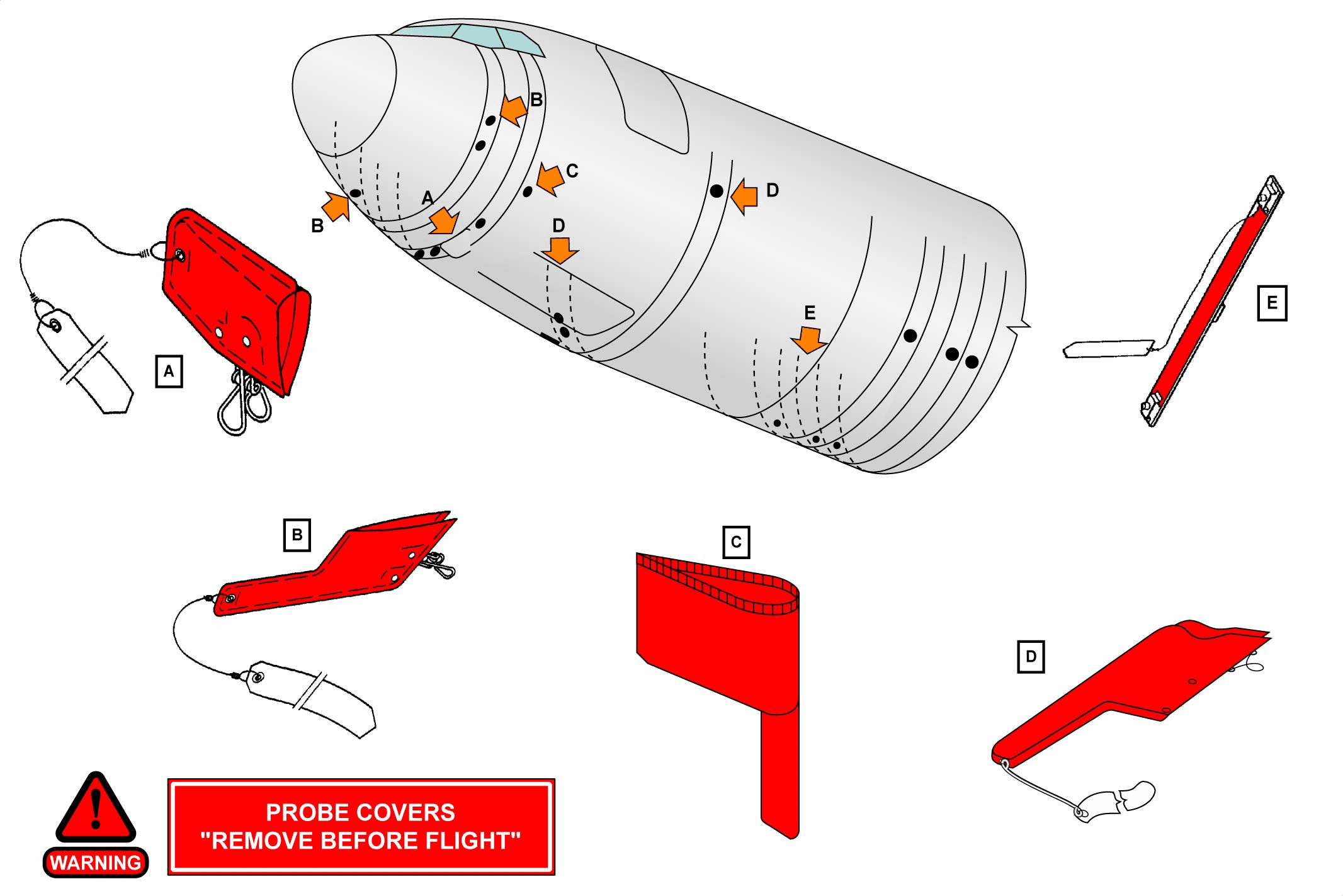
MAINTENANCE TIPS-PROBE HEAT SYSTEM
When the aircraft is parked, it is recommended to install protective covers on the air data probes (static ports, pitot probes, Angle Of Attack (AOA) probes, True Air Temperature (TAT) probes). The protective covers help to protect the probes from contamination. The covers should be marked with REMOVE BEFORE FLIGHT. Ground personnel must make sure that the covers are removed before flight or before the power is applied to the probes (engine start or ground test). The probe heat system operates automatically to power the air data probe heaters when at least one engine is running. It is also designed to operate automatically when the aircraft is in flight. During troubleshooting and ground operations, observe the following precautions:
– do not pull the Probe Heat Computer (PHC) or EIVMU or Landing Gear Control and Interface Unit (LGCIU) power supply circuit breakers, if you do so this causes the flight mode heating of the probes and static ports,
– make sure that the entire probe heat C/Bs are pulled (Static supply (28V DC), AOA supply, pitot supply and TAT supply (all 115V AC)).
维护提示-探头加热系统
飞机停放时,建议在空气数据探头(静态端口、皮托管探头、仰角 (AOA) 探头、总温 (TAT) 探头总温 (TAT) 探头)上安装保护盖。保护盖有助于保护探头免受污染。保护罩上应标有 “REMOVE BEFORE FLIGHT ”字样。地面人员必须确保在飞行前或向探头供电(发动机启动或地面测试)前取下保护盖。当至少有一台发动机运行时,探头加热系统会自动运行,为空气数据探头加热器供电。该系统还可在飞机飞行时自动运行。在故障排除和地面操作期间,请遵守以下注意事项:
– 请勿拉开探头加热计算机 (PHC) 或 EIVMU 或起落架控制和接口装置 (LGCIU) 电源断路器,否则会导致探头和静态端口在飞行模式下发热、
– 确保整个探头加热 C/B 拔下(静态电源 (28V DC)、AOA 电源、皮托管电源和 TAT 电源(均为 115V AC))。
WING ICE PROTECTION D/O (3)
GENERAL
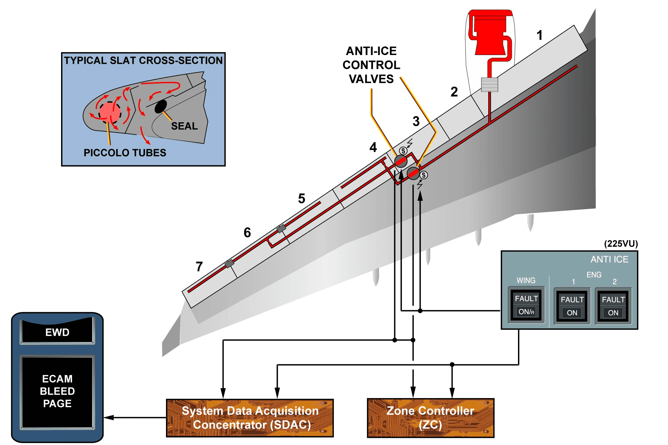
The wing ice protection system prevents the formation of ice on the leading edge of slats No. 4, 5, 6 and 7. The system uses bleed air from the engines to heat the slats. The system is divided into two subsystems, one for each wing. Each subsystem is divided into two parts:
– one for the slat 4,
– one for the slats 5, 6 and 7.
概况
机翼防冰系统可防止 4、5、6 和 7 号板条前缘襟翼结冰。该系统利用发动机引气加热襟翼。该系统分为两个子系统,每个机翼一个。每个子系统分为两部分:
– 一个用于襟翼 4、
– 一个用于襟翼 5、6 和 7。
WING ICE PROTECTION D/O (3)
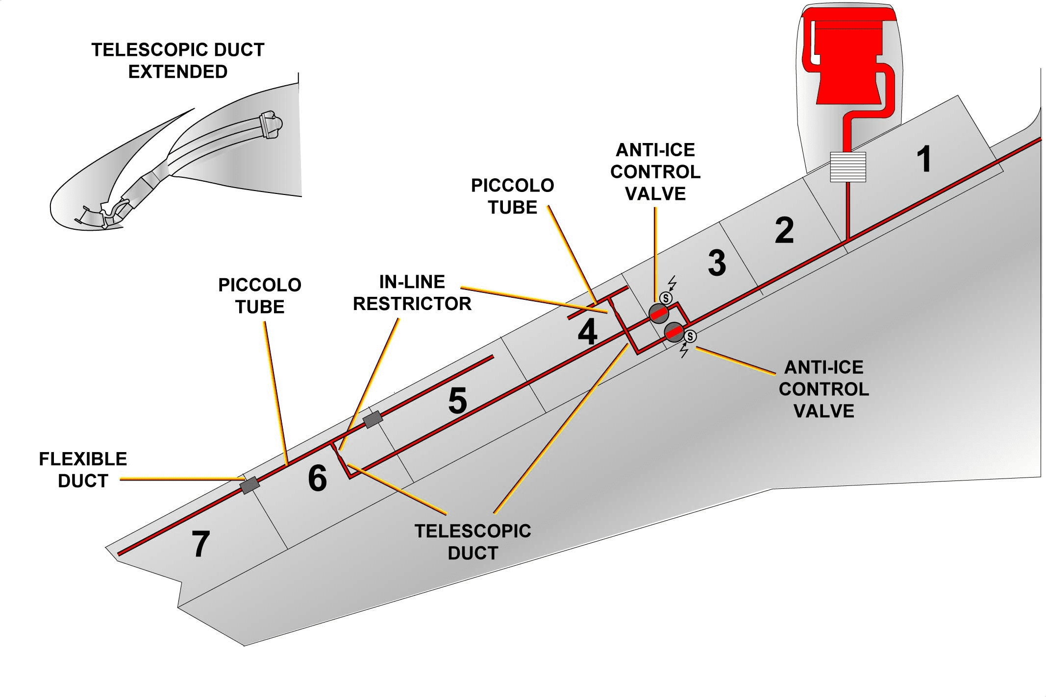
WING ANTI-ICE AIR DUCTING DESCRIPTION
In each wing, bleed air goes through two anti-ice control valves, a telescopic duct, an in-line restrictor, a flexible duct and piccolo tubes. The telescopic duct extends and retracts with the movement of the slats, and connects the air supply from the rigid duct to the slat 4 and 6 piccolo tubes. Two flexible ducts connect the piccolo tube in slat 6 to the piccolo tubes in slats 5 and 7. The restrictor is installed downstream of each anti-ice valve. It limits the airflow to the slats. The piccolo tube releases the air into the slats through holes along their FWD length.
机翼防冰空气管道说明
在每个机翼中,引气要经过两个防冰控制活门、一个伸缩管道、一个管路限流器、一个柔性管道和短笛管。伸缩管道随着襟翼的移动而伸缩,并将刚性管道的供气连接到襟翼 4 和 6 的短笛管。两个柔性管道将襟翼 6 中的短笛管与襟翼 5 和 7 中的短笛管连接起来。限流器安装在每个防冰活门的下游。它限制气流进入襟翼。短笛管通过沿板条横向长度方向的孔将空气释放到襟翼中。
WING ICE PROTECTION D/O (3)
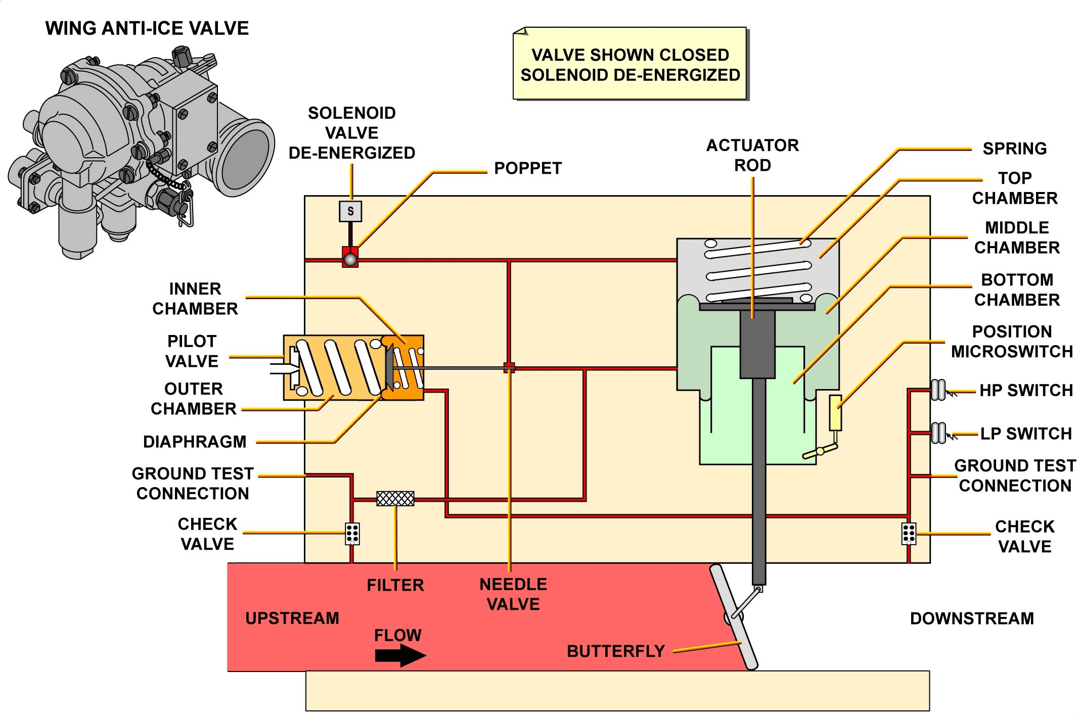
WING ANTI-ICE VALVE DESCRIPTION
The wing anti-ice control valve is of the butterfly type, electrically controlled and pneumatically operated. This valve fulfills the pressure regulation, the shut-off function and is spring-loaded closed. The valve outlet pressure is controlled at 22.5 ± 2.5 PSI.
Each valve is composed of:
– an actuator rod,
– a butterfly body,
– a pilot-valve assembly,
– a solenoid valve,
– a valve position microswitch,
– two pressure switches,
– two ground test connections.
The anti-ice valve is installed in the fixed leading edge of the wing and is accessible through a dedicated panel. For A/C dispatch, the valve can be manually locked in the open or closed position by means of a manual activation/deactivation device. A visual indicator shows the open or closed position of the valve butterfly.
机翼防冰活门说明
机翼防冰活门为蝶板型,电动控制,气动操作。该阀完成压力调节、关断功能,并采用弹簧载荷关闭。活门出口压力控制在 22.5 ± 2.5 PSI。
每个活门由以下部分组成
– 作动器杆、
– 一个蝶板壳体、
– 一个先导阀组件、
– 一个电磁阀、
– 一个活门位置微动开关、
– 两个压力开关、
– 两个接地测试接口。
防冰活门安装在机翼的固定前缘,可通过专用面板进入。在飞机放行时,可通过手动激活/停用装置将活门锁定在打开或关闭位置。可视指示器显示活门蝶板的打开或关闭位置。
PRESSURE REGULATING VALVE INTERNAL
OPERATION
When the solenoid valve is energized, the poppet moves to the open position. This movement connects the top chamber of the actuator to the atmosphere. The upstream bleed-air pressure is transmitted to the middle chamber of the actuator. This pressure is larger than the force of the spring in the top chamber, then the actuator rod moves up and opens the butterfly.
The pressure downstream of the butterfly is transmitted to the inner chamber of the pilot valve.
When this pressure becomes greater than the force of the spring in the outer pilot-valve chamber, the diaphragm extends, which moves the check valve. This connects the upstream pressure to the top chamber of the actuator. The increase of pressure in the top chamber causes the actuator rod to move down. This moves the butterfly near the closed position, which decreases the downstream pressure.
If the downstream pressure decreases, the spring (in the pilot-valve outer chamber) moves the needle to its initial position. The pressure in the top chamber decreases and the actuator rod moves up. This moves the butterfly to the open position.
When the solenoid is de-energized, the valve butterfly is closed.
压力调节活门原理
操作
电磁阀通电后,提升阀芯移动到打开位置。这一移动将作动器的上腔与大气连通。上游引气压力传递到作动器的中腔。该压力大于顶部腔室中弹簧的作用力,然后作动器杆向上移动并打开蝶板。
蝶板下游的压力传递到先导阀的内腔。
当该压力大于先导阀外腔弹簧的作用力时,膜片就会伸出,从而移动单向阀。这就将上游压力连接到了作动器的顶腔。顶部腔室中压力的增加导致作动器杆向下移动。这使得蝶板移动到关闭位置附近,从而降低了下游压力。
如果下游压力降低,(先导阀外腔中的)弹簧会将阀针移动到其初始位置。顶部腔室的压力降低,作动器杆向上移动。从而将蝶板移动到打开位置。
电磁阀断电后,蝶板关闭。
WING ICE PROTECTION D/O (3)
OPERATION
This part describes the wing anti-ice system in normal and abnormal operation and monitoring.
操作
本部分介绍机翼防冰系统在正常和异常操作下的运行和监控。
NORMAL OPERATION
The wing anti-ice system is normally used in flight and can also be tested on ground for 30 seconds.
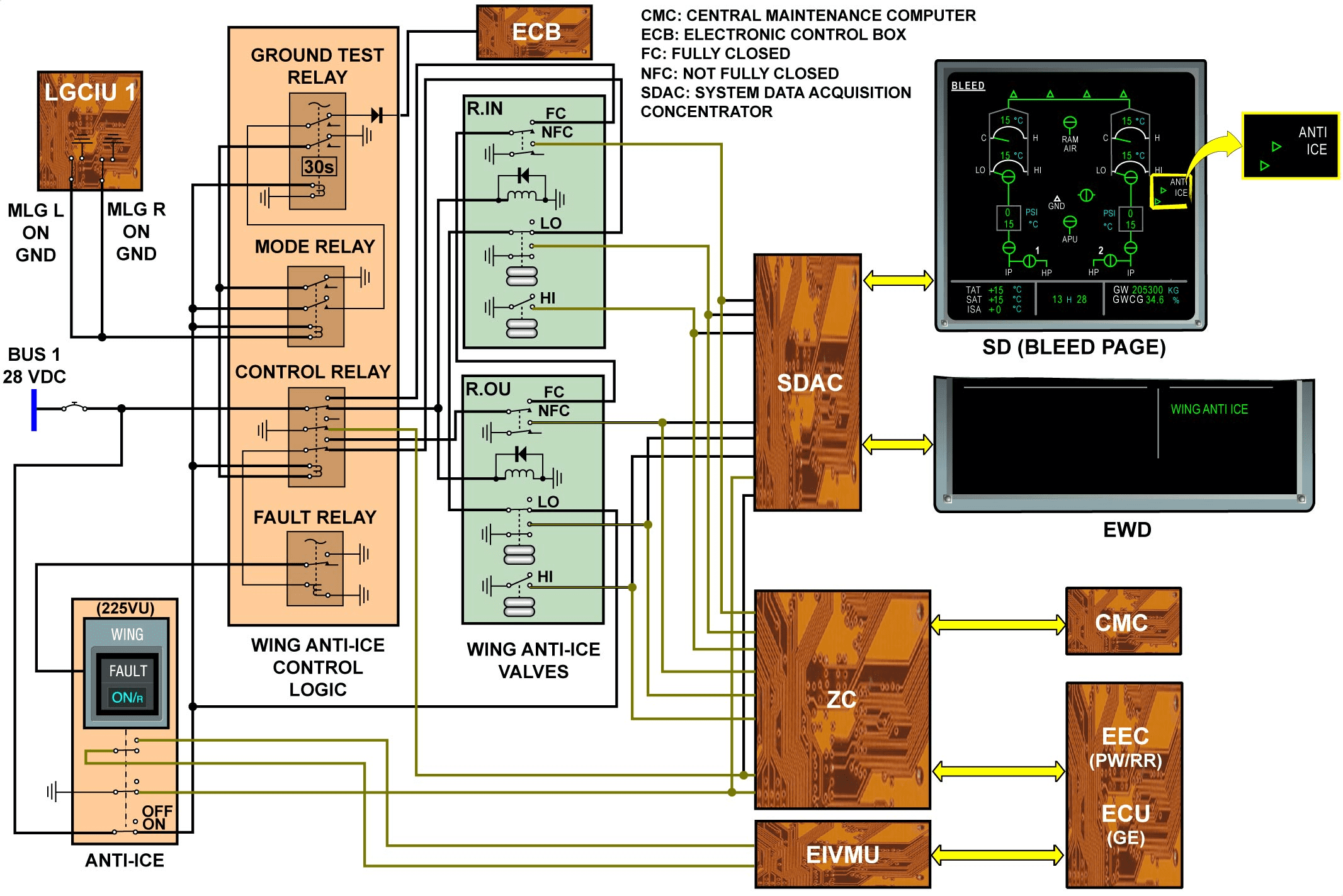
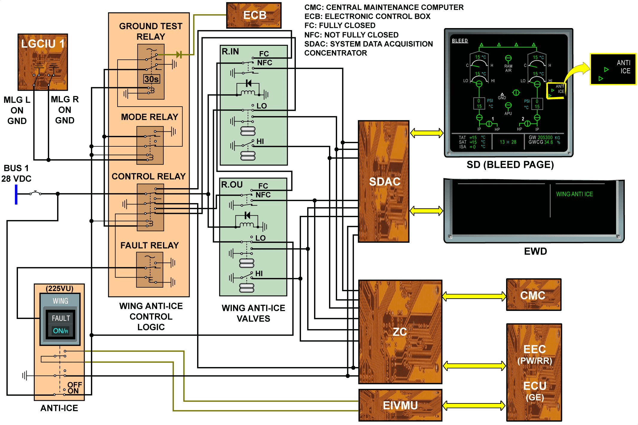
In flight: When the WING ANTI-ICE P/BSW is selected ON, the ON light comes on, the MODE and GROUND TEST relays are open and the CONTROL relay is closed. The valve solenoids are energized allowing the valves to open and to regulate at 22.5 ± 2.5 PSI. The WING ANTI ICE indication is displayed in green on the EWD. The Engine Electronic Controller (EEC) or the Engine Control Unit (ECU) acquires the P/BSW configuration through the Engine Interface and Vibration Monitoring Unit (EIVMU) for engine power increase according to the bleed demand. The Zone Controller (ZC) acquires discrete inputs from the wing anti-ice system to monitor the system and manage the bleed air. For each system, the valve position microswitch in the actuator body gives the butterfly position. This information is transmitted to the ECAM for ANTI ICE white indication and for green anti-ice valve symbol indications on the SD BLEED page. When the P/BSW is released out, the valve solenoids are de-energized and the valves close, no indication is displayed on the BLEED page of the SD.
On ground: Landing Gear Control and Interface Unit 1 (LGCIU1) sends a ground signal to the MODE relay.
When the WING ANTI-ICE P/BSW is selected ON, the MODE relay is energized and the GROUND TEST relay is open for 30 seconds. Consequently the CONTROL relay is also closed for 30 seconds allowing the valves to be energized for a limited time, thus preventing the slats from overheating. After 30 seconds, the GROUND TEST relay closes and de-energizes the valves through the CONTROL relay.
A functional test of the valve is possible using APU bleed air. For that purpose the APU Electronic Control Box (ECB) receives a discrete from the GROUND TEST relay to boost the bleed air during the ground wing anti-ice test.
正常操作
机翼防冰系统通常在飞行中使用,也可在地面进行 30 秒钟的测试。
飞行中 当机翼防冰 P/BSW 选择 ON 时,ON 指示灯亮起,MODE 和 GROUND TEST 继电器打开,CONTROL 继电器关闭。电磁阀通电,使活门打开并调节至 22.5 ± 2.5 PSI。机翼防冰指示在 EWD 上显示为绿色。发动机电子控制器 (EEC) 或发动机控制单元 (ECU) 通过发动机接口和振动监控单元 (EIVMU) 获得 P/BSW 配置,以便根据引气需求增加发动机功率。区域控制器 (ZC) 从机翼防冰系统获取离散输入,以监控系统并管理引气。对于每个系统,作动器壳体内的活门位置微动开关给出蝶板位置。该信息传输至 ECAM,用于 ANTI ICE 白色指示和 SD BLEED 页面上的绿色防冰活门符号指示。当 P/BSW 被释放出来时,活门电磁阀断电,活门关闭,SD 的 BLEED 页面上不会显示任何指示。
在地面上: 起落架控制和接口装置 1 (LGCIU1) 向模式继电器发送接地信号。
当机翼防冰 P/BSW 选择开启时,模式继电器通电,接地测试继电器打开 30 秒。因此,控制继电器也会关闭 30 秒,使阀门在有限的时间内通电,从而防止襟翼过热。30 秒后,接地测试继电器关闭,并通过控制继电器使活门断电。
可以使用 APU 引气对活门进行功能测试。为此,在地翼防冰测试期间,APU 电子控制盒(ECB)接收来自 GROUND TEST 继电器的离散信号,以增强引气。
This Page Intentionally Left Blank
WING ICE PROTECTION D/O (3)
OPERATION (continued)
ABNORMAL OPERATION
A failure is detected by a logic that combines the P/BSW switch position, the status of the valve position microswitch and the LP switch state.
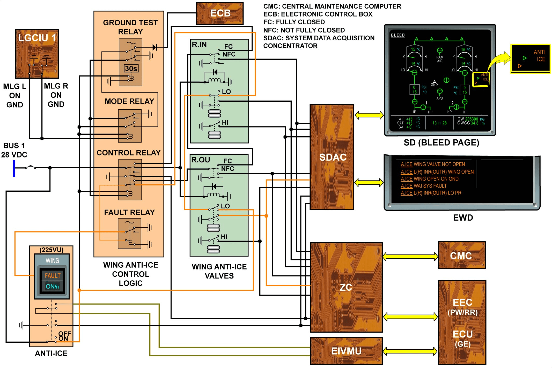
When the WING ANTI ICE P/BSW is selected ON and the valve is not open, the associated LP switch controls the FAULT relay to open. The P/BSW FAULT legend comes on. The A.ICE WING VALVE NOT OPEN warning message is displayed on the ECAM. On the BLEED page of the SD, the ANTI ICE indication is displayed in amber.
When the WING ANTI ICE P/BSW is selected off but the valve is not closed, as detected by the microswitch, the P/BSW FAULT legend comes on. The A.ICE L(R) INR(OUTR) WING OPEN warning message is triggered on the ECAM.
The wing anti-ice system is only used in flight so, on ground, the valves must be closed (except during test). In this condition, if the valves are open, the A.ICE WING OPEN ON GND warning message is triggered on the ECAM and the P/BSW FAULT legend comes on.
When a wing anti-ice control relay failure is detected, the A.ICE WAI SYS FAULT warning message is displayed on the ECAM. The P/BSW FAULT legend comes on.
When the system is ON and any valve is open with a LP detection (13.5 ± 0.5 PSI), the A.ICE L(R) INR(OUTR) LO PR message is displayed on the ECAM and the FAULT light comes on, on the P/BSW.
At the same time, fault messages are sent to the Central Maintenance Computer (CMC) via the ZC.
异常操作
故障由 P/BSW 开关位置、活门位置微动开关状态和 LP 开关状态相结合的逻辑进行检测。
当机翼防冰 P/BSW 选择为 ON 且活门未打开时,相关的 LP 开关会控制故障继电器打开。P/BSW 故障图例亮起。ECAM 上显示 A.ICE L(R) INR(OUTR) WING OPEN警告信息。在 SD 的引气页面上,防冰指示显示为琥珀色。
当选择关闭机翼防冰活门但微动开关检测到活门未关闭时,P/BSW FAULT 图例亮起。ECAM 上会触发机翼防冰 L(R) INR(OUTR) OPEN 警告信息。
机翼防冰系统仅在飞行中使用,因此在地面上,活门必须关闭(测试期间除外)。在这种情况下,如果活门打开,ECAM 上将触发 A.ICE WING OPEN ON GND 警告信息,同时 P/BSW FAULT 图例亮起。
当检测到机翼防冰控制继电器故障时,ECAM 上会显示 A.ICE WAI SYS FAULT 警告信息。P/BSW FAULT 图例亮起。
当系统开启且任何活门打开并检测到 LP(13.5 ± 0.5 PSI)时,ECAM 上显示 A.ICE L(R) INR(OUTR) LO PR 信息,P/BSW 上的 FAULT 指示灯亮起。
同时,故障信息将通过 ZC 发送至中央维护计算机 (CMC)。
WING ICE PROTECTION D/O (3)
OPERATION (continued)
MONITORING
On the ground, the wing ice-protection system test starts when the WING ANTI ICE P/BSW is selected ON. If the test continues for more than 35 seconds, the ECAM shows the warning message A.ICE GND TST OVRUN. The crew must then stop the operation of the wing ice-protection system to prevent heat damage to the slats.
During valve operation, if the downstream pressure increases to 31 ± 1 PSI, the related High Pressure (HP) switch gives an HP signal and the A.ICE L(R) INR(OUTR) HI PR warning message is displayed on the ECAM. The valve symbol and the ANTI ICE indication are displayed in amber color on the SD BLEED page.
In those two cases, with warning messages displayed on the ECAM, the P/BSW FAULT legend is not on
监控
在地面上,当机翼防冰 P/BSW 选择打开时,机翼防冰系统测试开始。如果测试持续超过 35 秒,ECAM 将显示警告信息 A.ICE GND TST OVRUN。这时机组人员必须停止机翼防冰系统的操作,以防止襟翼受热损坏。
在活门操作期间,如果下游压力增加到 31 ± 1 PSI,相关的高压 (HP) 开关会发出 HP 信号,ECAM 上会显示 A.ICE L(R) INR(OUTR) HI PR 警告信息。防冰活门符号和防冰指示以琥珀色显示在 SD 引气页面上。
在这两种情况下,ECAM 上显示警告信息时,P/BSW FAULT 图例不显示。

ENGINE AIR INTAKE ICE PROTECTION D/O (3)
GENERAL
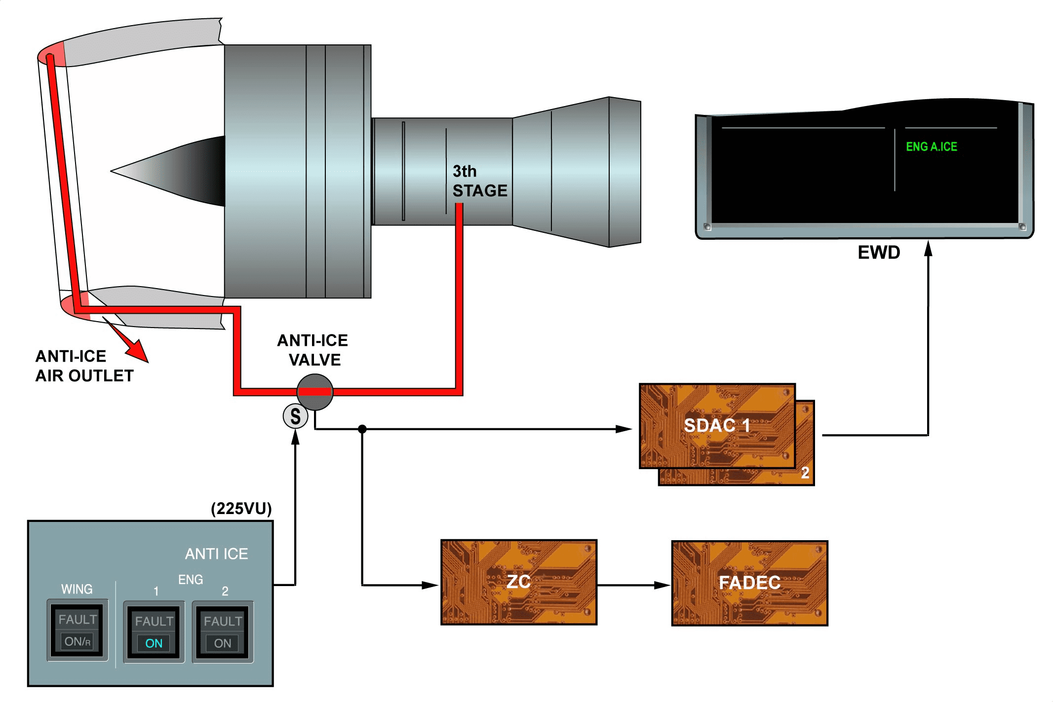
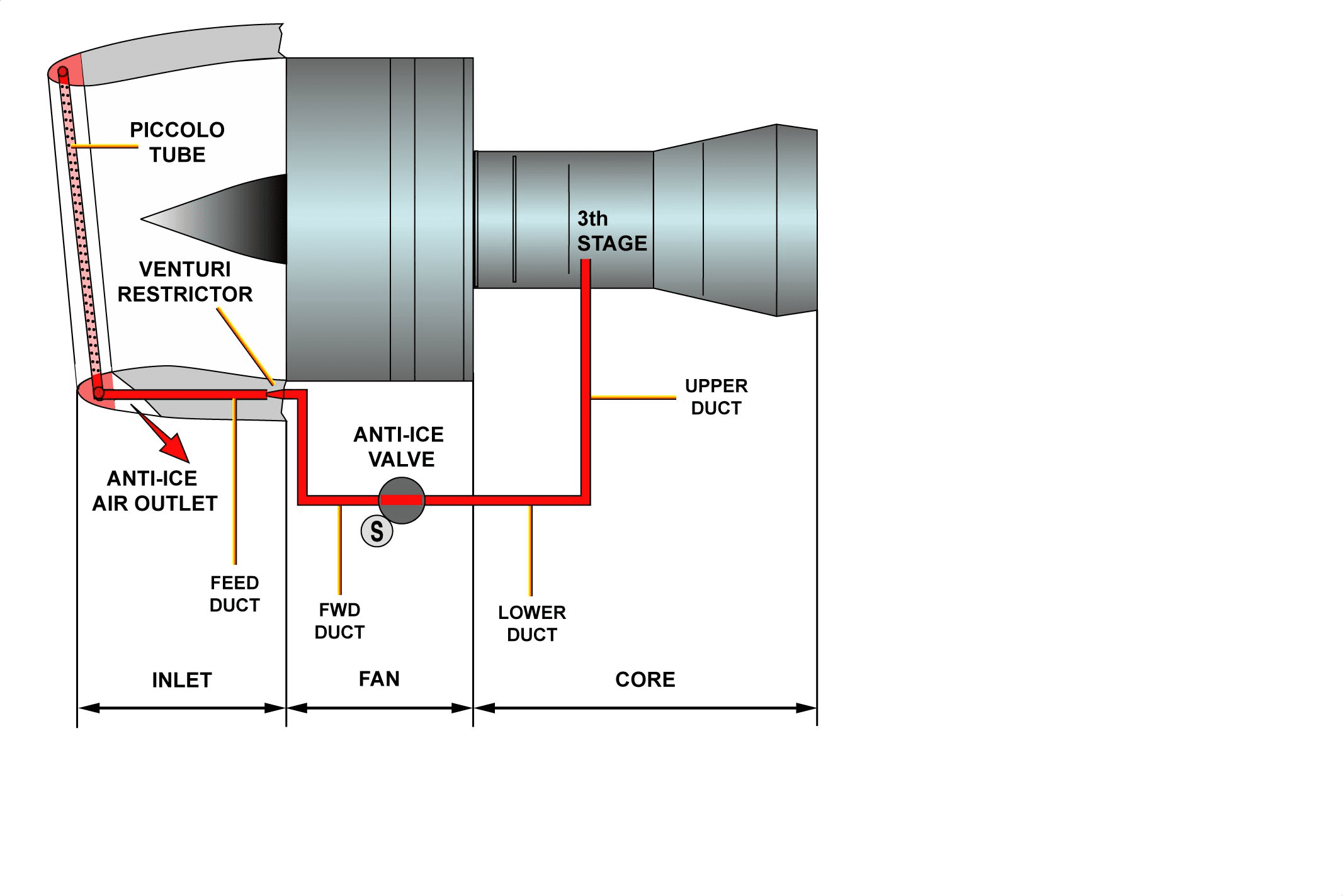
Engine air intake ice protection is achieved by heating the nose cowl lip with air bleed from the third stage of the engine compressor.
概况
发动机进气口结冰保护是通过利用发动机压缩机第三级的引气加热机头整流罩唇口来实现的。
ENGINE AIR INTAKE ICE PROTECTION D/O (3)
ENGINE ANTI-ICE AIR DUCTING DESCRIPTION
The air bleed from the engine compressor goes through duct sections, a pressure-regulating anti-ice valve and a venturi restrictor. Air is then sprayed through a piccolo tube into the nose cowl lip. The ducting is in four sections, three engine mounted (upper, lower and FWD) and one mounted in the fan cowl. The venturi restrictor is installed at the interface between the feed duct and the FWD duct. It limits the bleed airflow of the third stage in case of duct rupture.
发动机防冰空气管道说明
发动机压缩机的引气经过管道部分、压力调节防冰活门和文氏管节流器。然后,空气通过短笛管喷入前整流罩唇口。管道分为四个部分,三个安装在发动机上(上部、下部和 FWD),一个安装在风扇罩内。文氏管节流器安装在进气道和 FWD 管道的接口处。它可在管道破裂时限制第三级的引气流量。
ENGINE AIR INTAKE ICE PROTECTION D/O (3)
ENGINE ANTI-ICE VALVE DESCRIPTION
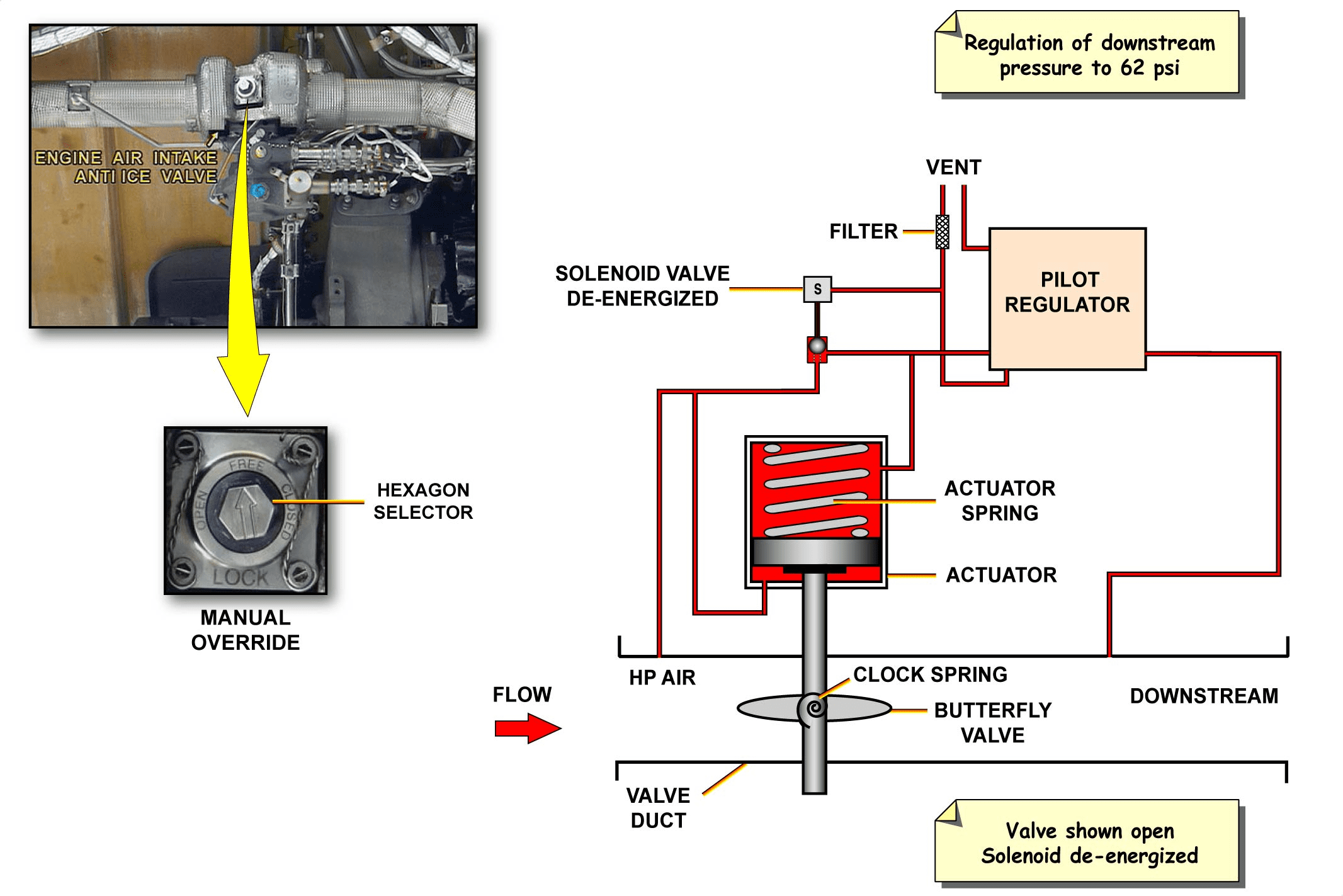
The engine anti ice valve is of the butterfly type, electrically controlled and pneumatically actuated. This valve performs both pressure regulation and shut-off and is spring-loaded open. When the valve operates, it regulates the maximum downstream air pressure to 62 psi. The engine anti-ice valve has:
– a butterfly valve sub-assembly,
– an actuator sub-assembly,
– a pilot regulator sub-assembly,
– HP and LP pressure switches,
– one filter,
– an ON/OFF solenoid.
The valve is installed on the lower left hand side of the engine. The bleed air source is taken on the HP compressor on the right hand side of the engine. The ENGine ANTI ICE panel gives access to the inlet tube. The fan cowl doors give access to the engine anti-ice valve.
The valve can be manually locked in the fully open or fully closed position by means of a hexagon selector. On the valve, a visual indicator shows the valve position.
发动机防冰活门说明
发动机防冰活门为蝶板式,由电控和气动作动。该活门同时具有压力调节和关断功能,并采用弹簧载荷开启。活门操作时,可将最大下游气压调节至 62 psi。发动机防冰活门有
– 一个蝶板活门组件、
– 作动器的子组件、
– 先导调节器组件、
– HP 和 LP 压力开关、
– 一个过滤器、
– 一个 ON/OFF 电磁阀。
活门安装在发动机左下方。引气气源取自发动机右侧的 HP 压缩机。通过发动机防冰面板可进入进气管。通过风扇罩门可以进入发动机防冰活门。
可通过六角选择器将活门手动锁定在全开或全关位置。活门上有一个可视指示器显示活门位置。
ENGINE ANTI-ICE INTERNAL OPERATION
When the solenoid is de-energized, the solenoid poppet moves to the spring-loaded retract position, and inlet air pressurizes the extend side of the actuator. This pressure combined with actuator spring force and the clock spring forces overcome the air pressure on the retract side of the actuator, so the piston moves to the open position. Once the valve is open, the pilot regulator makes sure that a constant outlet pressure of 62 psi is maintained by balancing the air pressure in the piston chambers.
When the solenoid is energized, the solenoid poppet moves to block the airflow to the extend side of the piston, thus the air pressure increases on the actuator retract side, so that the butterfly valve closes.
发动机防冰活门原理
当电磁阀断电时,电磁阀阀芯移动到弹簧载荷的缩回位置,进气向作动器的伸出侧施压。该压力与作动器弹簧力和时钟弹簧力相结合,克服了作动器缩回侧的空气压力,因此活塞移动到打开位置。活门打开后,先导阀调节器通过平衡活塞腔内的气压,确保保持 62 psi 的恒定出口压力。
当电磁阀作动的时候,电磁阀阀芯移动,阻止气流流向活塞的伸出侧,因此作动器缩回侧的气压增加,从而使蝶板关闭。
ENGINE AIR INTAKE ICE PROTECTION D/O (3)
ENGINE ANTI-ICE VALVE OPERATION
This topic describes the normal, abnormal operation and the engine anti-ice valve monitoring.
发动机防冰活门的操作
本主题介绍发动机防冰活门的正常、异常操作和监控。
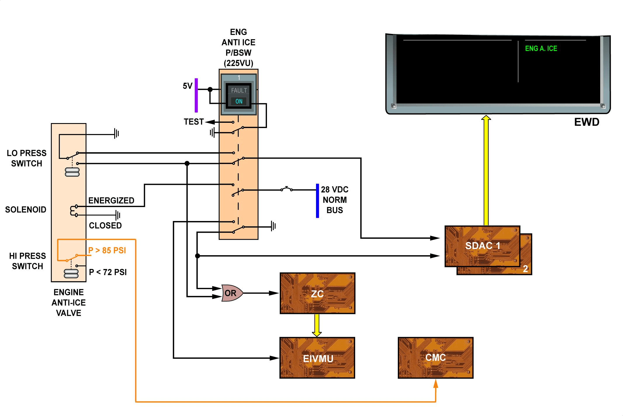
NORMAL OPERATION
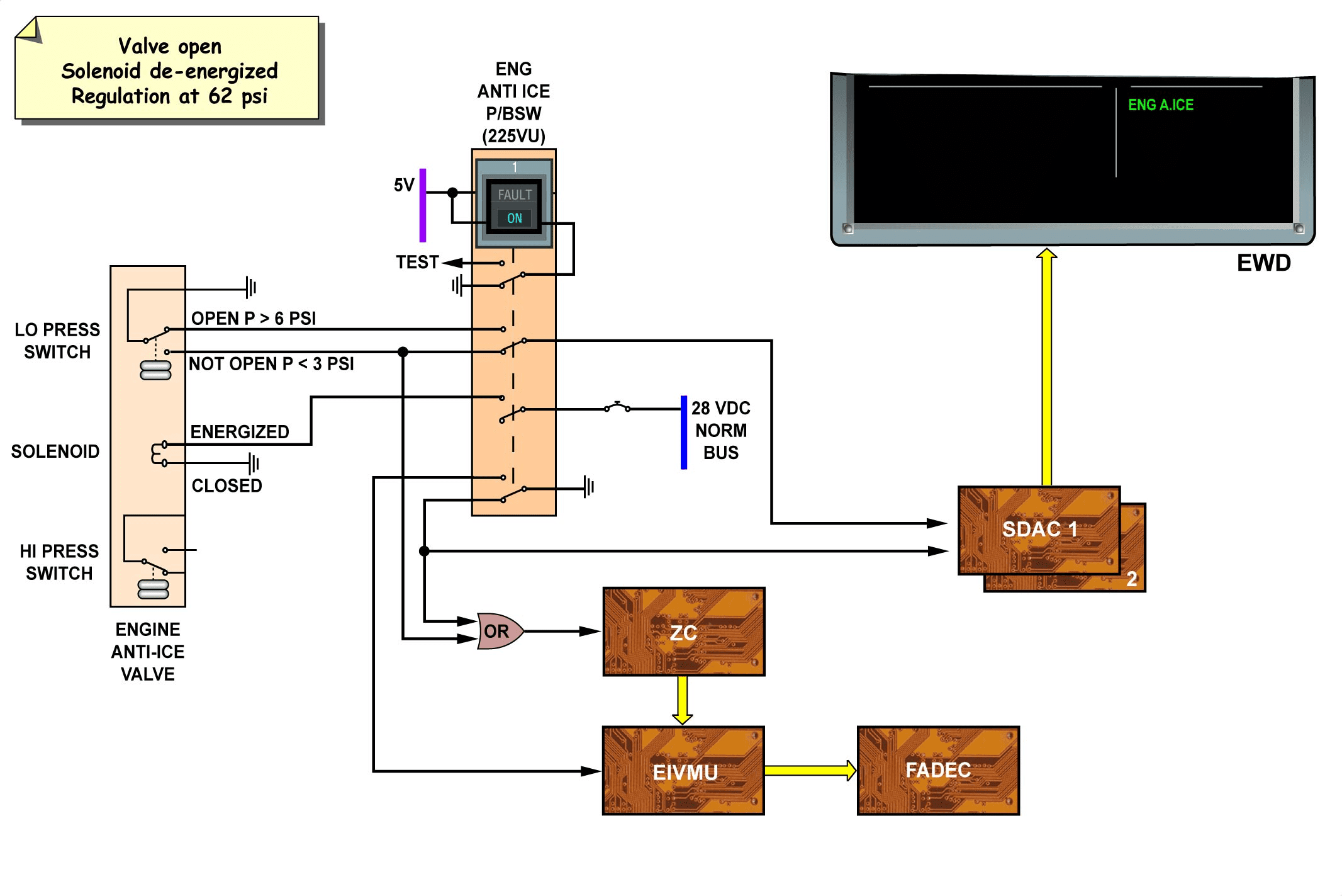
When the engine operates and the ENG ANTI ICE P/BSW is selected ON:
– the valve solenoid is de-energized,
– the valve opens and regulates at 62 psi.
The valve LP switch is used to detect the open position of the valve when the pressure is more than 6 psi. This information is transmitted to the ECAM for ENG A. ICE green memo indication on the EWD.
The Engine Interface and Vibration Monitoring Unit (EIVMU) acquires the configuration of the ENG ANTI ICE P/BSW and transmits it to the Full Authority Digital Engine Control (FADEC) system for selecting the continuous ignition.
The Zone Controller (ZC) uses the position of the ENG ANTI ICE P/BSW or the position of the engine anti-ice valve (provided by the LP switch) to calculate the bleed status coefficients.
When the ENG ANTI ICE P/BSW is selected off, the solenoid is energized and the valve closes. No indication is then displayed on the memo area of the EWD.
正常操作
当发动机操作且 ENG 防冰 P/BSW 选择 ON 时:
– 活门电磁阀断电、
– 活门打开并调节至 62 psi。
当压力超过 6 psi 时,活门 LP 开关用于检测活门的打开位置。该信息将传输至 ECAM,用于 ENG A. ICE 绿色备忘指示。
发动机接口和振动监控装置 (EIVMU) 获取 ENG 防冰 P/BSW 的配置,并将其传输给全权限数字发动机控制 (FADEC) 系统,以选择连续点火。
区域控制器 (ZC) 使用 ENG ANTI ICE P/BSW 的位置或发动机防冰活门的位置(由 LP 开关提供)来计算引气状态系数。
当 ENG ANTI ICE P/BSW 选择关闭时,电磁阀通电,活门关闭。此时 EWD 的备忘区不会显示任何指示。
ENGINE AIR INTAKE ICE PROTECTION D/O (3)
ENGINE ANTI-ICE VALVE OPERATION (continued)
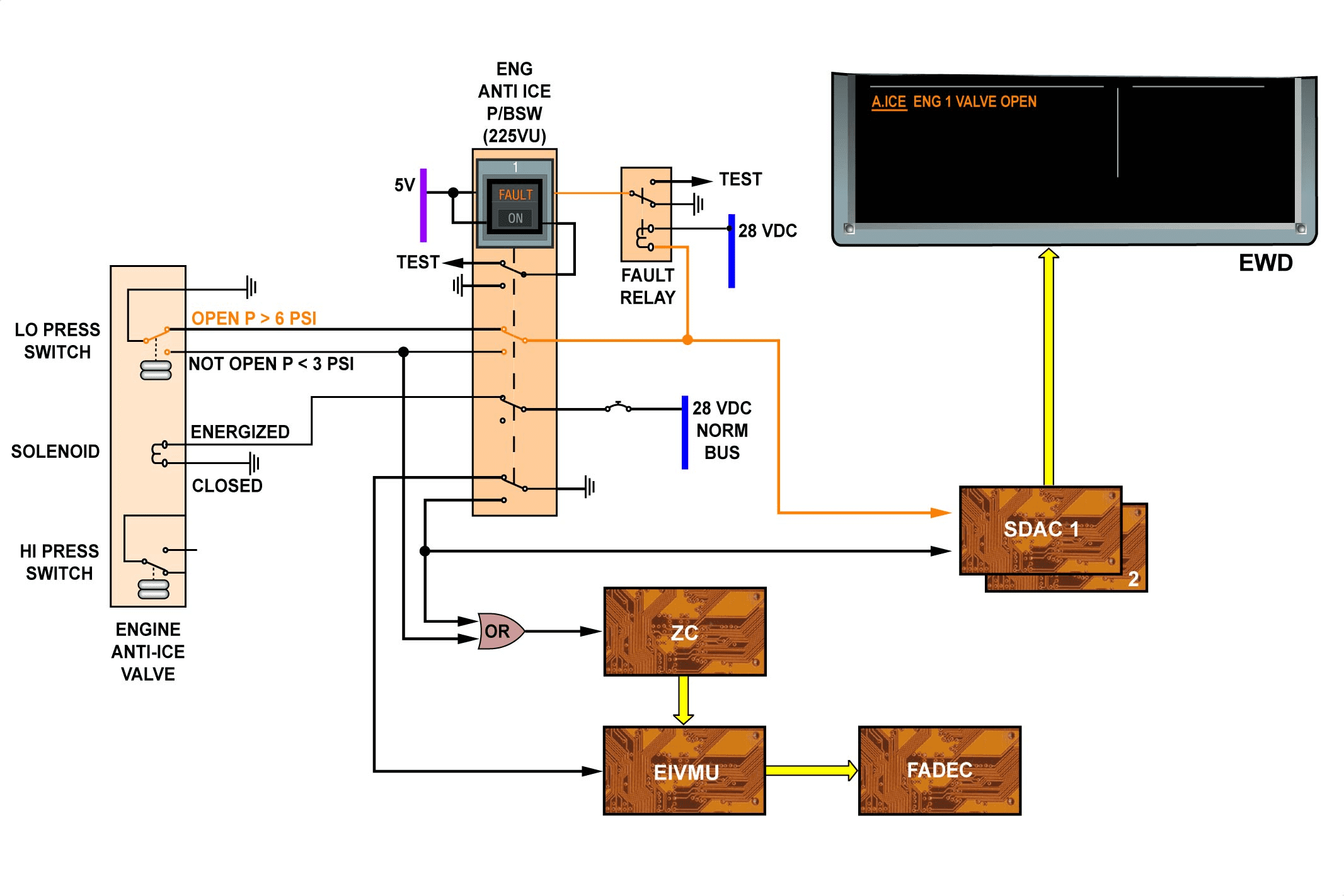
ABNORMAL OPERATION
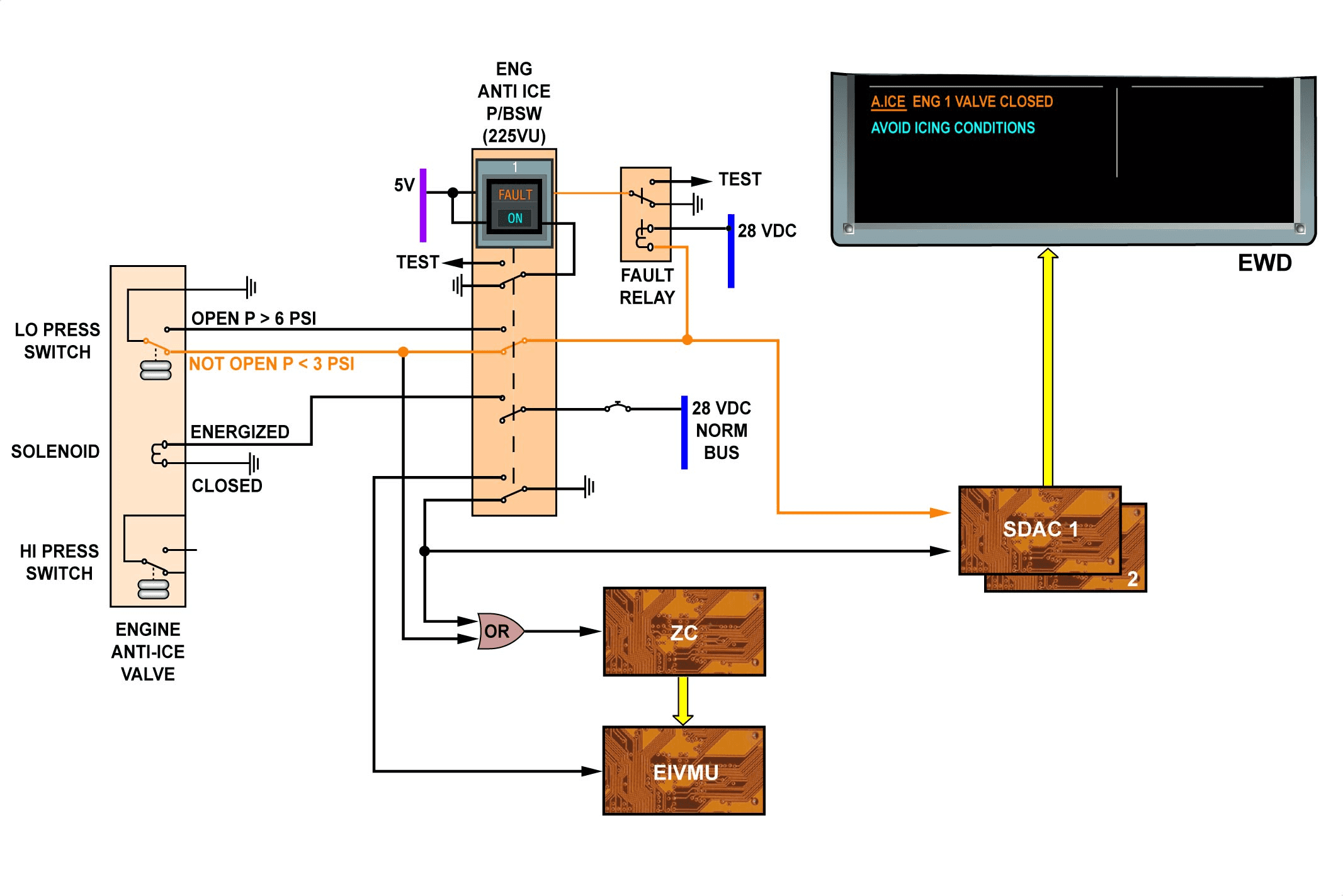
A failure is detected by a logic that combines the P/BSW configuration and the pressure downstream of the engine anti-ice valve.
When the ENG ANTI ICE P/BSW is selected ON but the valve is not open, the P/BSW FAULT legend comes on through the FAULT relay. The A.ICE ENG 1 (or 2) VALVE CLOSED and AVOID ICING CONDITIONS warning messages are triggered on the EWD.
When the ENG ANTI ICE P/BSW is selected off but the valve is not closed, the P/BSW FAULT legend comes on. Then, the A. ICE ENG 1 (or 2) VALVE OPEN warning message is triggered on the EWD.
异常操作
通过结合 P/BSW 配置和发动机防冰活门下游压力的逻辑来检测故障。
当选择 ENG ANTI ICE P/BSW 开启但活门未打开时,P/BSW 故障图例通过故障继电器亮起。EWD 上会触发 A.ICE ENG 1(或 2)VALVE CLOSED 和 AVOID ICING CONDITIONS 警告信息。
当选择关闭 ENG 防冰活门但阀门未关闭时,P/BSW FAULT 图例亮起。然后,EWD 上会触发 A. ICE ENG 1(或 2)活门打开警告信息。
This Page Intentionally Left Blank
ENGINE AIR INTAKE ICE PROTECTION D/O (3)
ENGINE ANTI-ICE VALVE OPERATION (continued)
ENGINE ANTI-ICE VALVE MONITORING
The valve switch monitors the regulation function of the valve. The pressure operating setting of this switch is 85 psi (maximum rising pressure) to 72 psi (minimum falling pressure).
If the engine anti-ice valve downstream pressure increases above the normal regulation range and reaches 85 psi, a fault message is transmitted to the Central Maintenance Computer (CMC).
发动机防冰活门监控
活门开关监控活门的调节功能。该开关的压力操作设置为 85 psi(最大上升压力)至 72 psi(最小下降压力)。
如果发动机防冰活门下游压力上升超过正常调节范围并达到 85 psi,则会向中央维护计算机 (CMC) 发送故障信息。
PROBE ICE PROTECTION D/O (3)
GENERAL
The function of the probe ice protection system is to provide probe electrical heating to prevent ice formation. An electrical heating system integral with each probe operates to maintain probe efficiency. The Probe Heat Computer (PHC) ensures permanent monitoring of probes automatically. In cases of severe icing conditions on ground, automatic operation can be overridden by means of the Probe & Windows Heat P/BSW.
概况
探头结冰保护系统的功能是提供探头电加热,防止结冰。每个探头都配有一个电加热系统,用于保持探头的效率。探头加热计算机 (PHC) 可确保自动对探头进行永久监控。在地面,严重结冰的情况下,可通过探头和窗口加热 P/BSW 覆盖自动操作。
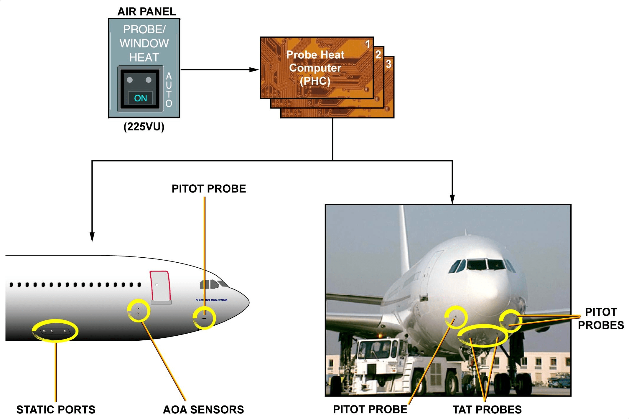
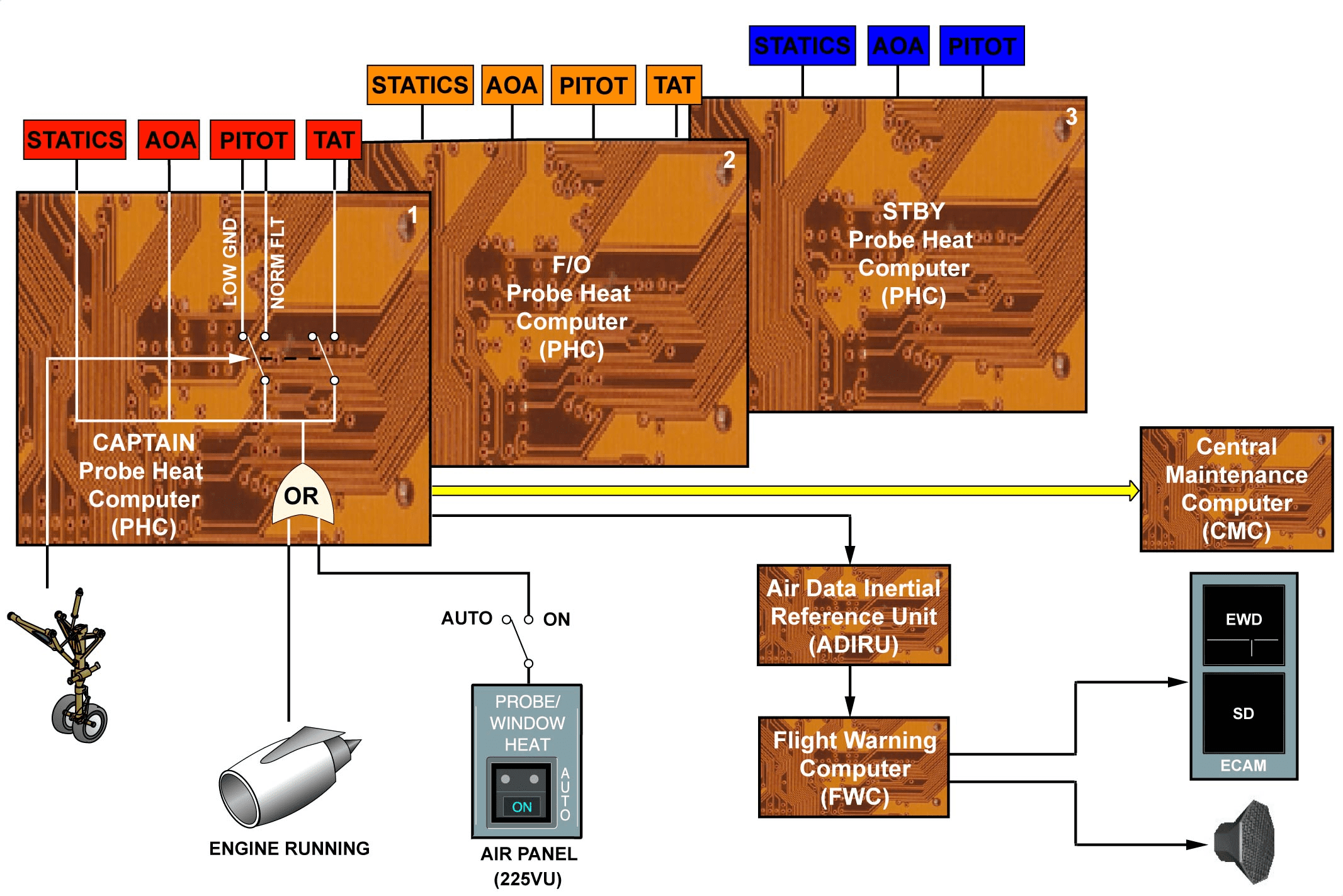
PROBE ICE PROTECTION D/O (3)
CONTROL AND OPERATION
Captain, First Officer and standby probes are heated by independent systems controlled by a PHC. The standby system has no Total Air Temperature (TAT) probe.
The heated probes are: static ports, Angle Of Attack (AOA), pitot and TAT. Probes and static ports are automatically heated when engine 2 or 3 is started on ground or in flight using the landing gear status. TAT probes are heated only in flight and pitot probes have 2 heating levels, low on ground and normal in flight. The Probe & Windows Heat P/BSW overrides the automatic operation.
控制和操作
机长、大副和备用探头由 PHC 控制的独立系统加热。备用系统没有总温 (TAT) 探头。
加热探头包括:静态端口、仰角 (AOA)、皮托管和 TAT。在地面或飞行中使用起落架状态启动 2 号或 3 号发动机时,探头和静态端口会自动加热。TAT 探头仅在飞行中加热,皮托管探头有两个加热等级,在地面时为低等级,在飞行中为正常等级。探头和窗口加热 P/BSW 可覆盖自动操作。
INDICATING
In case of a probe heating fault, the PHC sends an output to the Flight Warning Computer (FWC), via the Air Data/Inertial Reference Unit (ADIRU), which generates an ECAM and an aural warning. The PHC also transmits fault messages to the Central Maintenance Computer (CMC).
指示
如果探头加热出现故障,PHC 会通过大气数据/惯性基准组件 (ADIRU) 向飞行警告计算机 (FWC) 发送输出信号,后者会发出 ECAM 和声音警告。PHC 还向中央维护计算机 (CMC) 发送故障信息。
WINDSHIELD A.ICE/DEFOGGING & RAIN PROT D/O (3)
COCKPIT WINDOWS ANTI-ICE DEFOGGING AND RAIN PROTECTION GENERAL
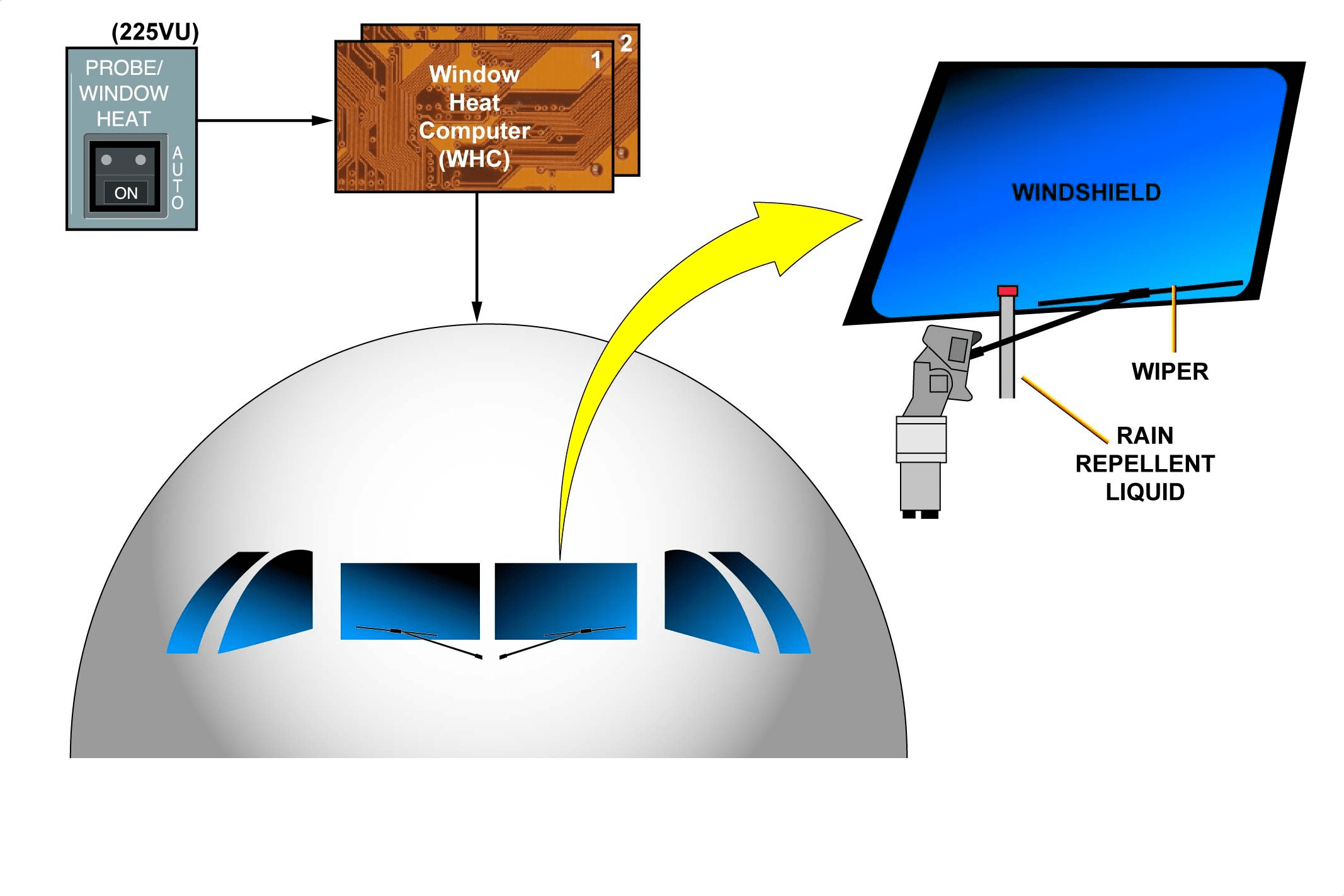
The anti-icing and defogging system keeps a clear visibility through the windshield and windows in icing or foggy conditions. This is achieved by electrical heating of the windshield and windows. In heavy rain conditions, rain removal from the windshield is ensured by two independent wipers and a rain repellent liquid, stored in a pressurized bottle, which may be sprayed onto the windshield to improve visibility.
驾驶舱窗户防冰除雾和防雨
在结冰或起雾的情况下,防冰除雾系统可通过挡风玻璃和窗户保持清晰的视野。这是通过对挡风玻璃和窗户进行电加热实现的。在大雨条件下,挡风玻璃上的雨水可通过两个独立的雨刮器和储存在加压瓶中的防雨液清除,防雨液可喷洒在挡风玻璃上,以提高能见度。
WINDSHIELD A.ICE/DEFOGGING & RAIN PROT D/O (3)
ANTI-ICE AND DEFOGGING CONTROL AND MONITORING
Heating is automatically initiated at first engine start-up and stops at last engine shut-down. The PROBE & WINDOW HEAT P/BSW overrides the automatic operation.
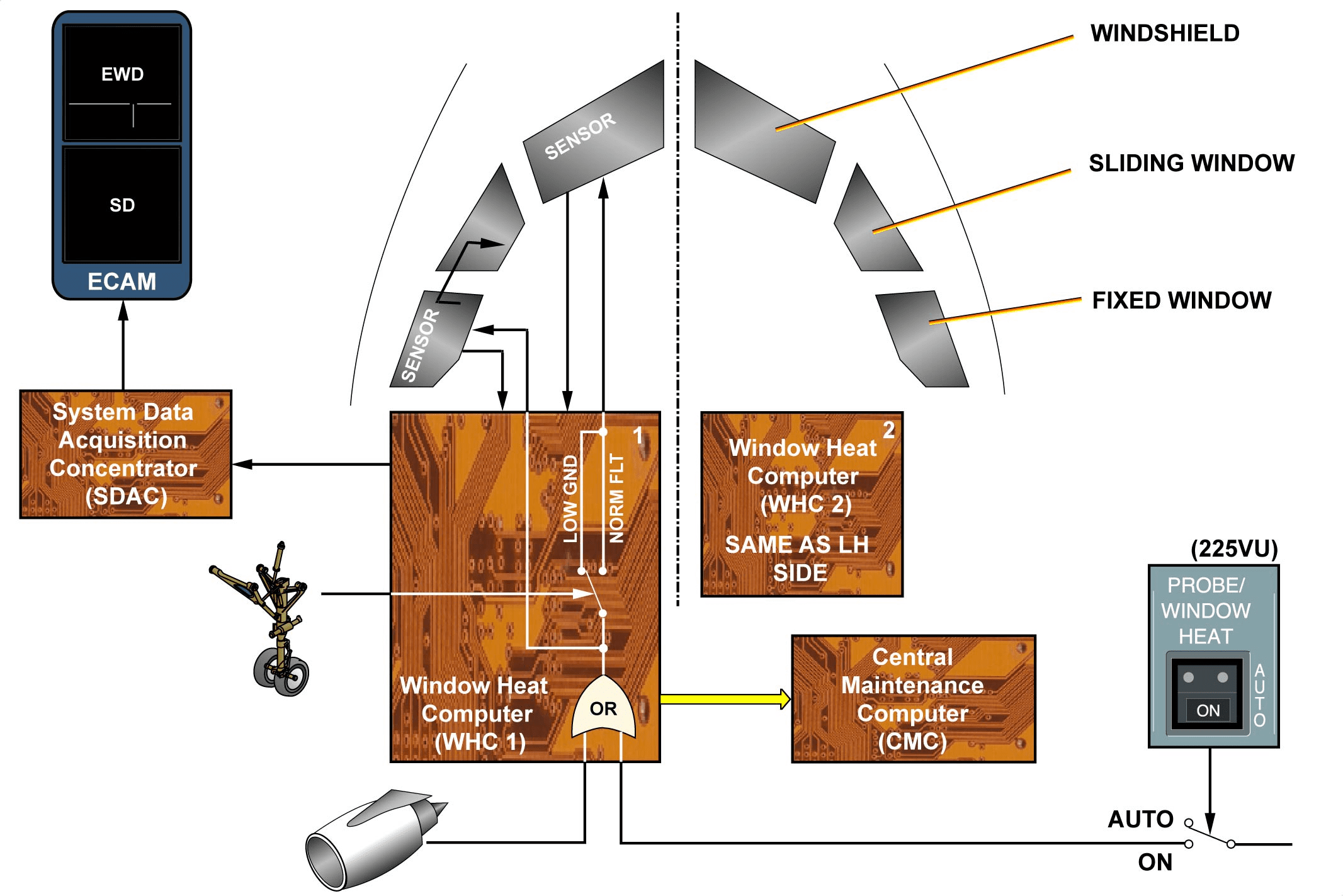
Monitoring and overheat protection control are achieved by two fully independent Window Heat Computers (WHCs), one for each side. For the windshield, there are 2 heating levels, low on ground and normal in flight and only one heating level for windows. Fixed and sliding windows are heated in series. Ground/flight information is provided by the status of the landing gear.
The WHC controls the windshield and windows temperature heating using temperature feedback from the temperature sensors. There are 3 sensors fitted on the windshield and 3 sensors fitted on each fixed window.
The WHC is connected to two sensors of the windshield and one sensor of each fixed window. If one sensor of the windshield fails, the WHC automatically switches to the second sensor without any maintenance action (first sensor failure identified by corresponding class 3 Central Maintenance Computer (CMC) fault message). The third sensor has to be connected manually at terminal block level. In case of a window-heating fault, the WHC sends an output to the ECAM via the System Data Acquisition Concentrator (SDAC). The WHC also transmits fault messages to the CMC.
防冰和除雾控制与监测
首次启动发动机时自动启动加热,最后一次关闭发动机时停止加热。PROBE & WINDOW HEAT P/BSW可超控自动操作。
监控和过热保护控制由两个完全独立的窗户加热计算机(WHC)实现,每侧一个。对于挡风玻璃,有两个加热等级,分别是地面低温和飞行中的正常温度,而对于窗户则只有一个加热等级。固定窗户和滑动窗户是串联加热的。地面/飞行信息由起落架状态提供。
WHC 通过温度传感器的温度反馈来控制挡风玻璃和窗户的温度加热。挡风玻璃上安装有 3 个传感器,每个固定窗上安装有 3 个传感器。
WHC 与挡风玻璃上的两个传感器和每个固定窗户上的一个传感器相连。如果挡风玻璃上的一个传感器出现故障,WHC 会自动切换到第二个传感器,而无需采取任何维护措施(第一个传感器故障由相应的 3 级中央维护计算机(CMC)故障信息识别)。第三个传感器必须在接线板上手动连接。在出现窗户加热故障时,WHC 通过系统数据采集集中器 (SDAC) 向 ECAM 发送输出。WHC 还向 CMC 发送故障信息。
WINDSHIELD A.ICE/DEFOGGING & RAIN PROT D/O (3)
WIPER SYSTEM
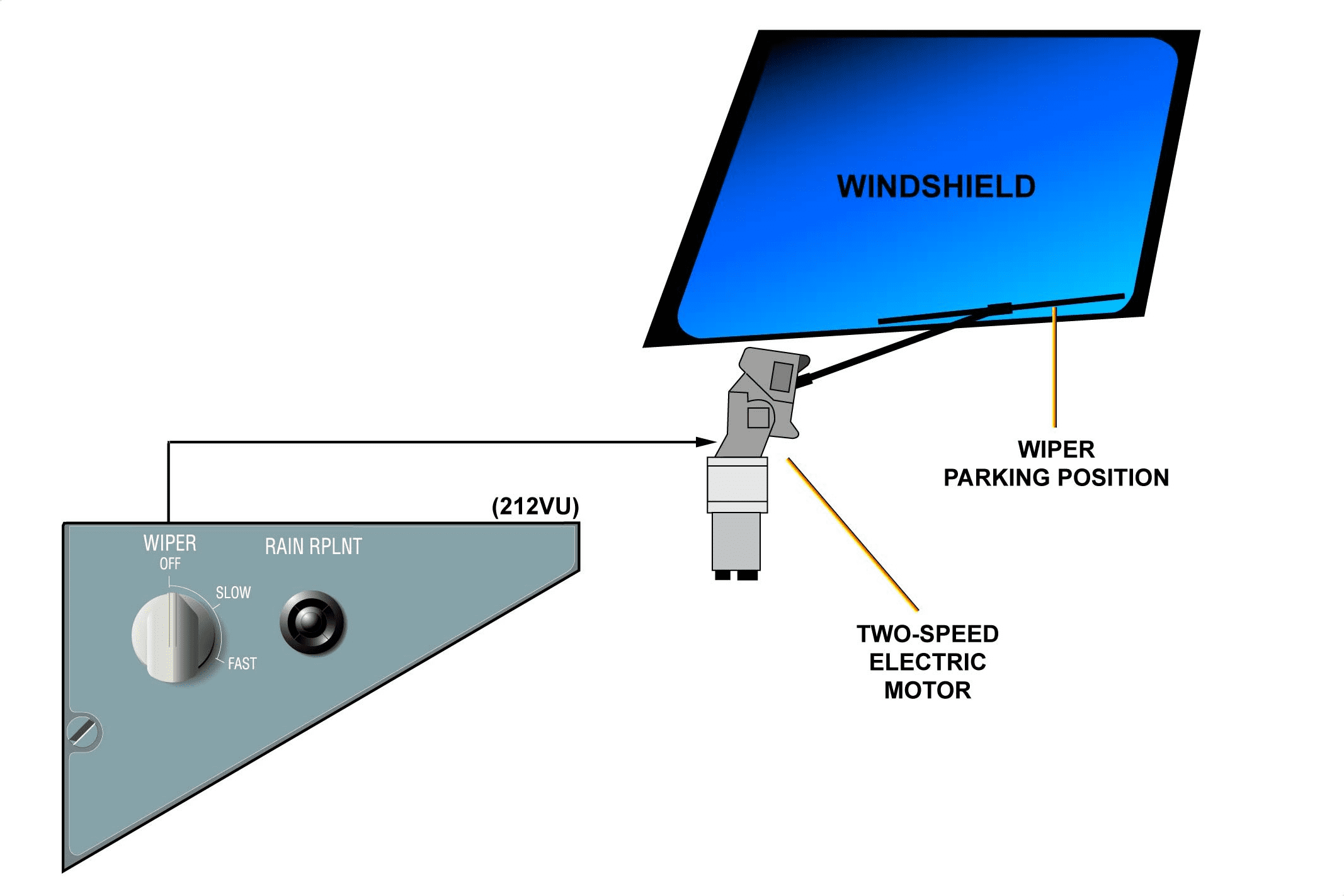
Each wiper is independently actuated by a two-speed electric motor controlled by the WIPER control selector located on the overhead panel. SLOW or FAST speed can be selected. When the selector is set to OFF, the wiper stops in the parking position on the lower part of the windshield and is lifted off the aircraft structure.
雨刷系统
每个雨刷均由一个双速电动马达独立作动,该马达由顶置面板上的雨刷控制选择器控制。可选择SLOW或FAST。当选择器设置为关闭时,雨刷停在挡风玻璃下部的停放位置,并从飞机结构上抬起。
WINDSHIELD A.ICE/DEFOGGING & RAIN PROT D/O (3)
RAIN REPELLENT SYSTEM
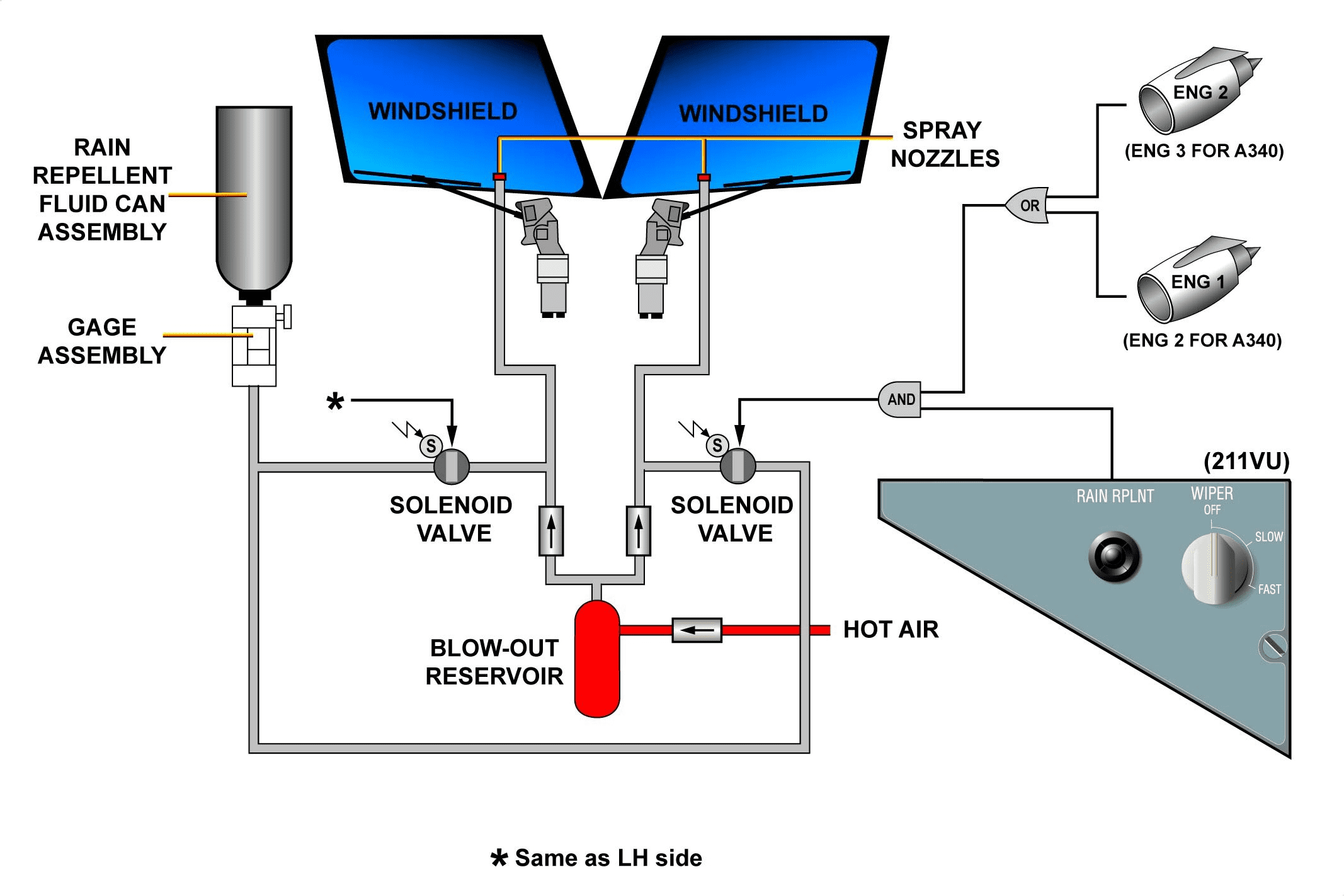
The rain repellent system is composed of a pressurized rain repellent can assembly for storage, a gage assembly for pressure indicating, time controlled solenoid valves, 2 spray nozzles and a blow-out reservoir, which enables the spray nozzles to be purged with hot air. When the rain repellent P/B is pressed in, the solenoid valve opens for a short time. This causes a measured quantity of rain repellent liquid to be sprayed onto the related windshield. On ground, the rain repellent system is inhibited when engines are shut down.
防雨系统
防雨系统由一个用于储存的加压防雨罐组件、一个用于显示压力的压力表组件、一个时间控制电磁阀、2 个喷嘴和一个吹出储气罐组成,吹出储气罐可以用热空气对喷嘴进行吹扫。压入驱雨剂 P/B 时,电磁阀会短时间打开。这将导致一定量的防雨液喷洒到相关的挡风玻璃上。在地面上,当发动机关闭时,防雨系统会被抑制。
POTABLE & WASTE WATER ICE PROTECTION D/O (3)
GENERAL
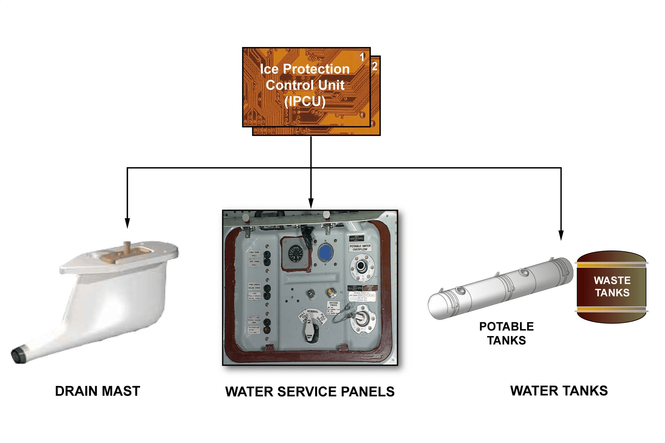
An automatic electrical water ice protection system is installed to prevent ice formation in the water pipes and drain masts in flight or on ground at given freezing temperatures. Two Ice Protection Control Units (IPCUs) control and monitor this system.
通用
为防止水管和排水桅杆在飞行中或地面给定的冰冻温度下结冰,安装了一套自动电水结冰保护系统。两个防冰控制单元(IPCU)对该系统进行控制和监控。
POTABLE & WASTE WATER ICE PROTECTION D/O (3)
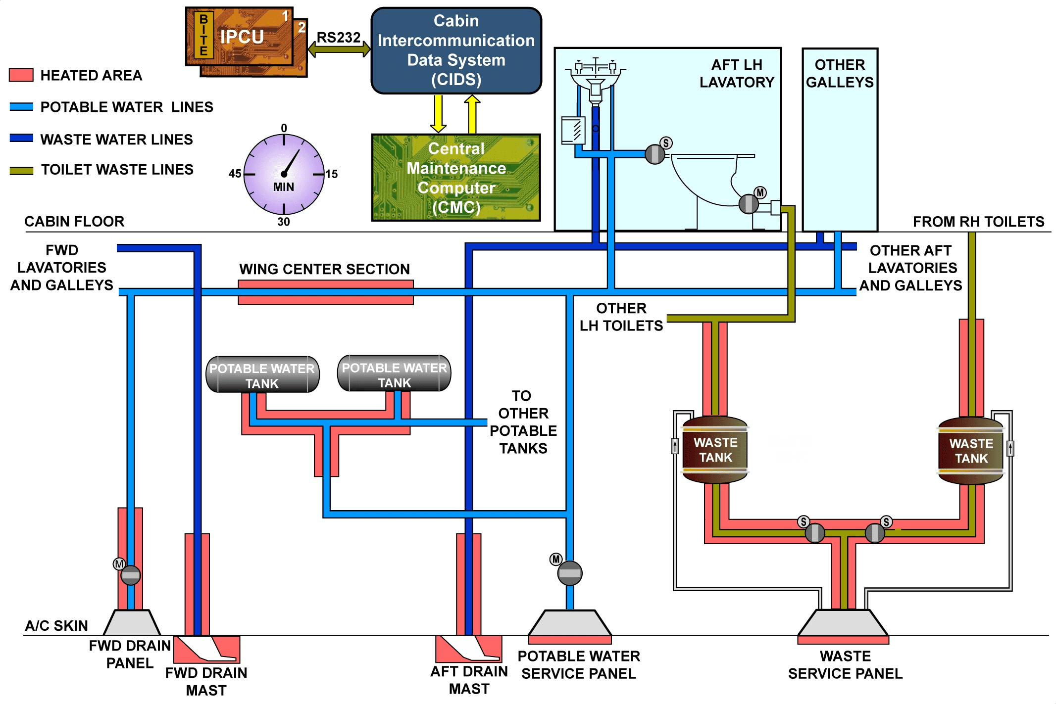
ELECTRICAL HEATING ELEMENTS
Electrical heating elements equipped with temperature sensors, are fitted on the following components:
– water lines,
– drain masts,
– water service panel,
– waste tank drain tubes and valve,
– toilet waste lines.
CONTROL
Electrical heating elements are controlled and monitored by two IPCUs. The IPCUs turn the electrical heating on or off depending on information from temperature sensors. Programmable temperature thresholds are stored in the IPCUs.
A BITE test is performed every 5 minutes by the IPCUs, which transmit the system status to the Cabin Intercommunication Data System (CIDS) and to the Centralized Maintenance System (CMS).
电加热元件
电加热元件配有温度传感器,安装在下列部件上:
– 水管
– 排水桅杆
– 配水盘、
– 废水箱排水管和阀门、
– 厕所排污管道。
控制
电加热元件由两个 IPCU 控制和监控。IPCU 根据温度传感器提供的信息开启或关闭电加热装置。可编程的温度阈值存储在 IPCU 中。
IPCU 每 5 分钟进行一次 BITE 测试,并将系统状态传送到机舱内部通信数据系统 (CIDS) 和中央维护系统 (CMS)。
ESCAPE SLD LOCKING MECHANISM ICE PROT D/O (3)
GENERAL
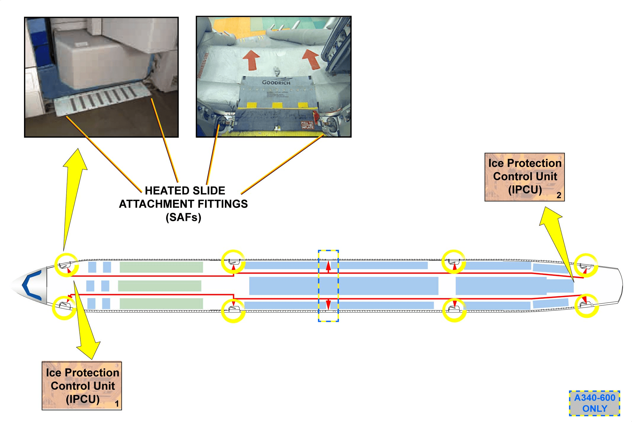
To make sure that the escape slide locking mechanism can be disarmed at the opening of the door, the system prevents ice formation of condensation water in the Slide Attachment Fittings (SAFs). Each passenger door has two heated SAFs. The overwing-emergency exits (only on the A340-600) have no heated SAFs.
The SAFs lock the escape slide girt-bar to the doorframe structure, when the door-emergency control handle is in the ARMED position. They are installed by the doors sill area of each passenger/crew door. Two Ice Protection Control Units (IPCU 1 and IPCU 2) control and monitor the 16 SAFs.
通用性
为确保在车门打开时能解除逃生滑锁装置,系统会防止滑动连接装置 (SAF) 中的冷凝水结冰。每个乘客门都有两个加热的滑动连接装置。上方紧急出口(仅在 A340-600 上)没有加热 SAF。
当车门紧急控制手柄处于 “ARMED”位置时,SAF 将逃生滑轨的横梁锁定在门框结构上。它们安装在每个乘客/机组车门的门框区域。两个防冰控制单元(IPCU 1 和 IPCU 2)控制和监控 16 个 SAF。
ESCAPE SLD LOCKING MECHANISM ICE PROT D/O (3)
DESCRIPTION
The escape slide locking mechanism with the ice protection system is composed of 16 SAFs and 2 IPCUs.
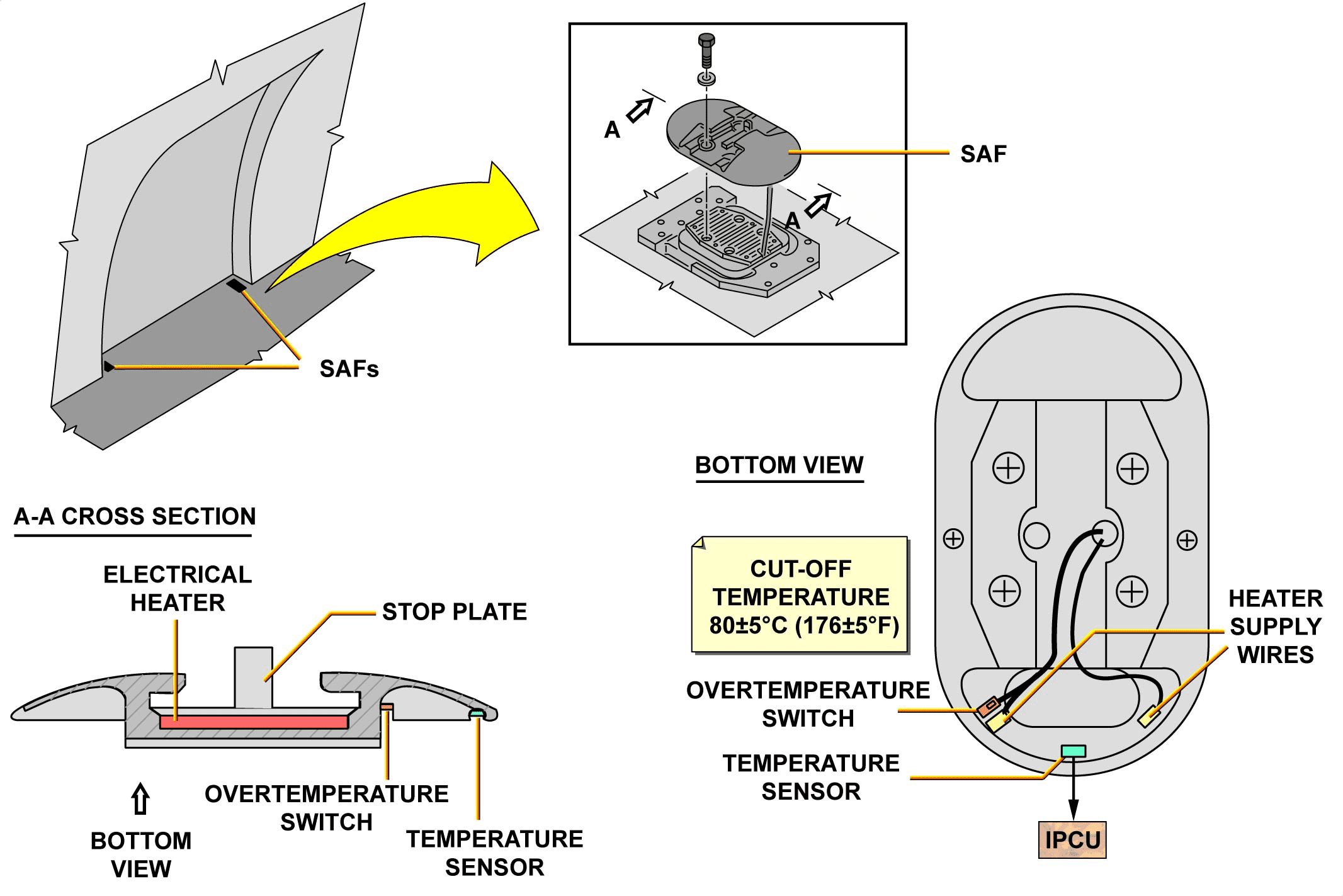
SLIDE ATTACHMENT FITTINGS
One SAF has:
– one electrical heater,
– one temperature sensor,
– one overtemperature switch.
The electrical heater is installed between the bottom of the SAF and the SAF stop plate. The temperature sensor and the overtemperature switch are installed on the lower side of the SAF:
– the temperature sensor is connected to one IPCU. It continuously measures the temperature of the SAF,
– the overtemperature switch protects the heater element in case of a malfunction of the temperature sensor. The cut-off temperature is 80±5°C (176±5°F).
描述
带有防冰系统的逃生滑梯锁定装置由 16 个 SAF 和 2 个 IPCU 组成。
滑道连接装置
一个 SAF 有
– 一个电加热器
– 一个温度传感器、
– 一个超温开关。
电加热器安装在 SAF 底部和 SAF 挡板之间。温度传感器和超温开关安装在 SAF 的下侧:
– 温度传感器连接到一个 IPCU。它持续测量 SAF 的温度、
– 超温开关在温度传感器发生故障时保护加热元件。截止温度为 80±5°C (176±5°F)。
ESCAPE SLD LOCKING MECHANISM ICE PROT D/O (3)
DESCRIPTION (continued)
ICE PROTECTION CONTROL UNIT LOCATION
Two IPCUs are installed:
– one on the right hand side of the Avionics Compartment,
– and one on the right hand side of the Aft Cargo Compartment.
The forward IPCU controls and monitors the SAFs of the following four-passenger/crew doors: 1RH, 1LH, 2RH and 2LH. The aft IPCU controls and monitors the SAFs of the following four-passenger/crew doors: 3RH, 3LH, 4RH and 4LH.
防冰控制单元的位置
两个 IPCU安装在:
– 一个安装在航空电子设备舱的右侧、
– 一个在机尾货舱右侧。
前部 IPCU 控制和监控以下四个乘客舱门/机组舱门的 SAF:1RH、1LH、2RH 和 2LH。后部 IPCU 控制和监控以下四个乘客舱门/机组人员舱门的 SAF:3RH、3LH、4RH 和 4LH。

ESCAPE SLD LOCKING MECHANISM ICE PROT D/O (3)
DESCRIPTION (continued)
ICE PROTECTION CONTROL UNIT FUNCTION
The primary functions of the IPCUs are:
– heating regulation,
– temperature range adjustment (customer option),
– heater and sensor disable/enable test,
– heater current monitoring,
– Cabin Intercommunication Data System (CIDS) interface,
– power-up reset.
防冰控制单元的功能
冰保护控制单元的主要功能是
– 加热调节
– 温度范围调节(客户选项)
– 加热器和传感器禁用/启用测试、
– 加热器电流监控、
– 客舱互通数据系统 (CIDS) 接口、
– 开机复位。

ESCAPE SLD LOCKING MECHANISM ICE PROT D/O (3)
NORMAL OPERATION
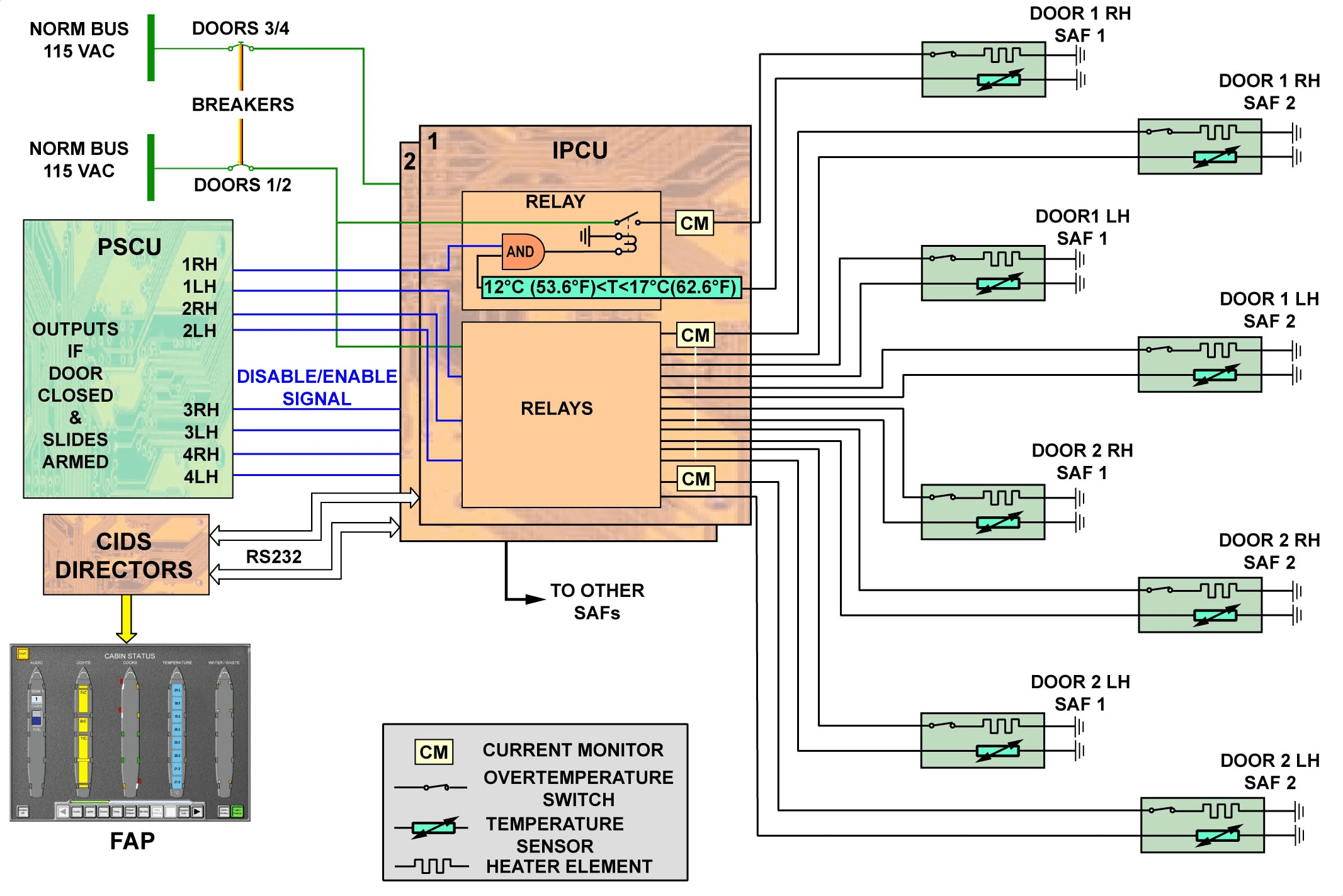
Each IPCU receives a 115 VAC power supply used for operation and heater supply.
The Escape Slide Locking Mechanism with the Ice Protection System has an interface with the Door Proximity Switch Control Unit (PSCU) for door and slide arming signal information.
The IPCU controls each door heating SAF by closing the associated power relay when the following conditions are met:
– the associated door is closed and the associated emergency control handle is in the “armed” position (enable signal from PSCU),
– the SAF temperature sensor reads less than 12°C (53.6°F).
When the temperature is higher than 17°C (62.6°F), the IPCU switches the heating off.
MONITORING
Each IPCU can be tested either automatically every five minutes or manually from the MCDU through the CIDS GROUND SCANNING page. Each heater element electrical current is monitored by its associated IPCU for status fault detection. If a fault is detected, a fault message will be then displayed on the FAP.
正常操作
每个 IPCU 接收用于操作和加热器供应的 115 VAC 电源。
带有防冰系统的逃生滑梯锁定装置有一个与门接近开关控制单元 (PSCU) 连接的接口,用于获取门和滑梯就位信号信息。
当满足以下条件时,IPCU 通过关闭相关的电源继电器来控制每个门加热 SAF:
– 相关的门已关闭,且相关的紧急控制手柄处于 “armed”位置(来自 PSCU 的启用信号)、
– SAF 温度传感器读数低于 12°C (53.6°F)。
当温度高于 17°C (62.6°F) 时,IPCU 将关闭加热装置。
监控
每个 IPCU 可每五分钟自动测试一次,也可由 MCDU 通过 CIDS GROUND SCANNING 页面手动测试。每个加热元件的电流都由其相关的 IPCU 监控,以检测状态故障。如果检测到故障,故障信息将显示在 FAP 上。
ICE DETECTION D/O (3)
GENERAL
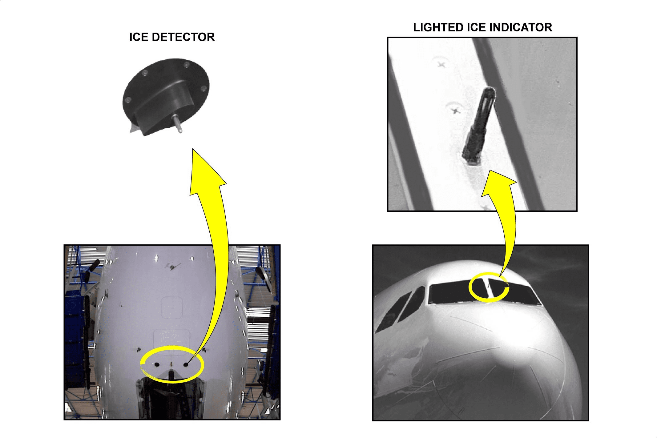
The purpose of the ice detection system is to provide better detection of icing conditions and fuel saving by cutting off the anti ice system when it is no longer necessary. Two ice detectors are installed on the fuselage in front of the nose gear. A visual detection system informs the crew that icing conditions are encountered, by accretion of ice on a visual lighted indicator.
通用性
冰探测系统的目的是更好地探测结冰情况,并在不再需要防冰系统时将其切断,从而节省燃料。机身上在前起落架前安装了两个结冰探测器。可视探测系统通过可视指示灯上的积冰通知机组人员遇到结冰情况。
ICE DETECTION D/O (3)
OPERATION
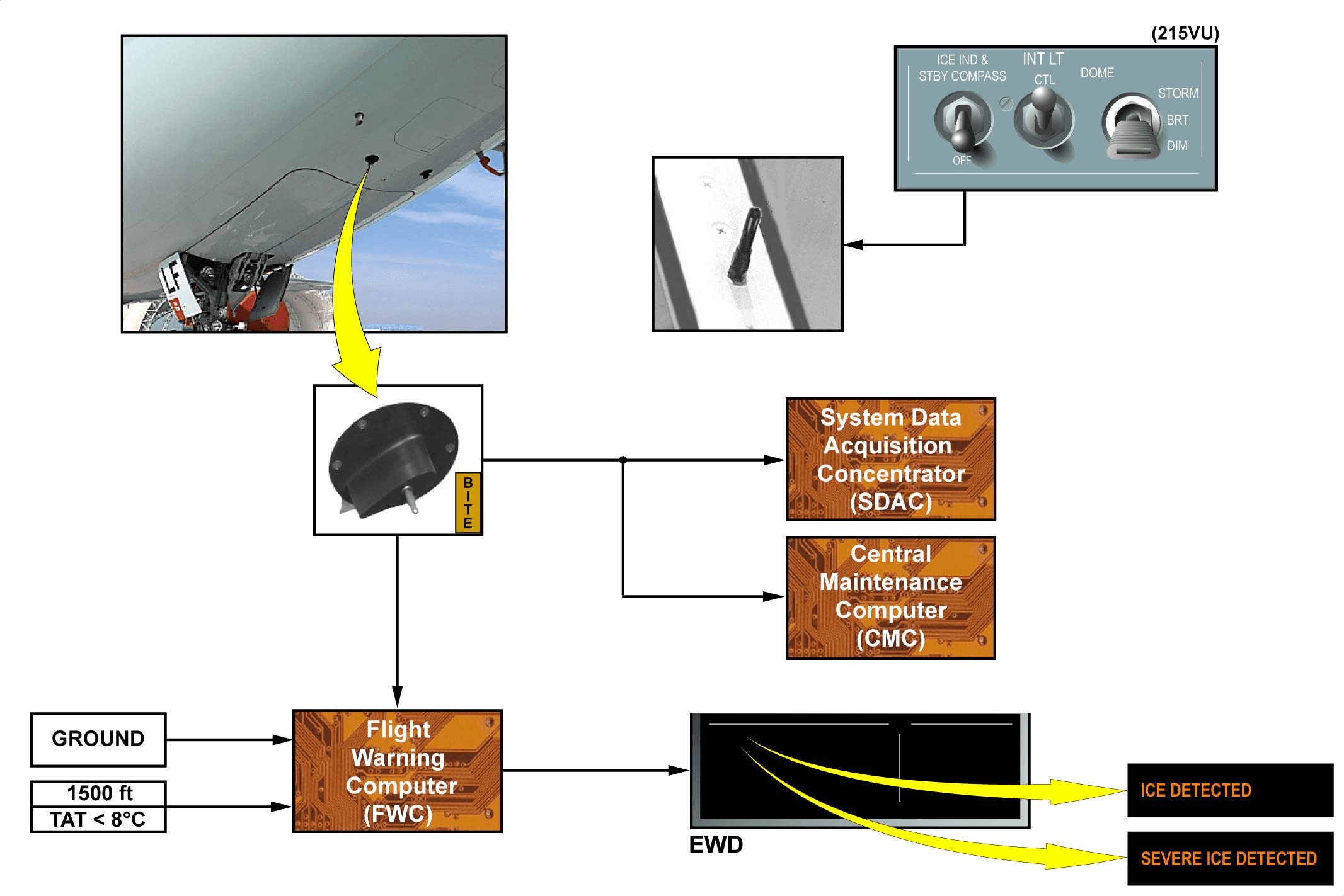
The ice detection system is directly connected to the Flight Warning Computer (FWC) to send warning messages to the crew on the EWD.
The ice detection system operates at electrical power-up. It sends warnings in flight above 1500 ft and when the Total Air Temperature (TAT) is below 8 degrees Celsius. The system is inhibited on ground.
INDICATION AND MONITORING
There are two levels of indication: ICE DETECTED corresponding to an elementary detection and SEVERE ICE DETECTED corresponding to 7 elementary detections. These two levels are displayed on the EWD.
A fault signal is displayed when the two ice detectors are faulty. Each ice detector is equipped with a BITE function for continuous monitoring. Fault signals are sent to the System Data Acquisition Concentrator (SDAC) and to the Central Maintenance Computer (CMC).
VISUAL LIGHT INDICATOR
The ICE IND AND STBY COMPASS switch controls the illumination of the lighted icing indicator.
操作
冰探测系统直接连接到飞行警告计算机 (FWC),以便在 EWD 上向机组人员发送警告信息。
冰探测系统在接通电源时操作。在飞行高度超过 1500 英尺以及总温 (TAT) 低于 8 ℃ 时,该系统会发出警告。该系统在地面上处于抑制状态。
指示和监控
有两级指示: ICE DETECTED对应一次基本探测,SEVERE ICE DETECTED对应 7 次基本探测。这两个级别显示在 EWD 上。
当两个结冰检测器出现故障时,会显示故障信号。每个结冰检测器都配有 BITE 功能,用于持续监测。故障信号被发送到系统数据采集集中器 (SDAC) 和中央维护计算机 (CMC)。
视觉指示灯
ICE IND AND STBY COMPASS开关控制结冰指示灯的亮度。
ICE & RAIN PROTECTION SYSTEM BASE MAINTENANCE(3)
INTRODUCTION
One base servicing procedure is described in this module. This task concerns the adjustment of the Water Ice Protection Data Unit (WIPDU) coding switches and “enable micro switches” following the components replacement.
This task is accomplished to set the WIDPU in function of the A/C heating circuits configuration.
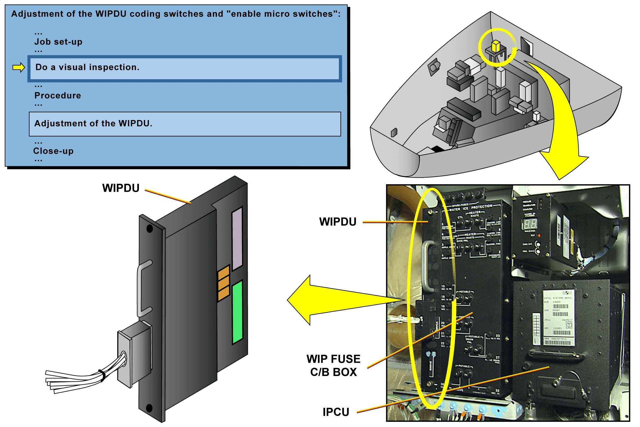
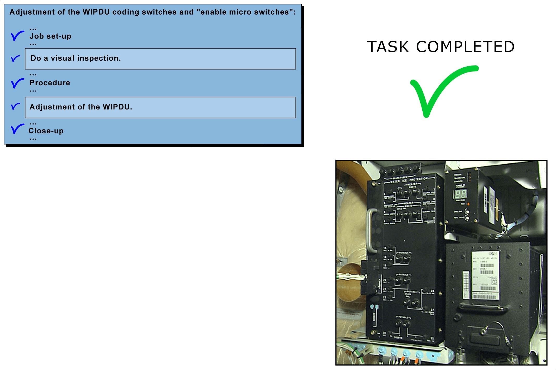
ADJUSTMENT OF THE WIPDU CODING SWITCHES AND “ENABLE MICRO SWITCHES”
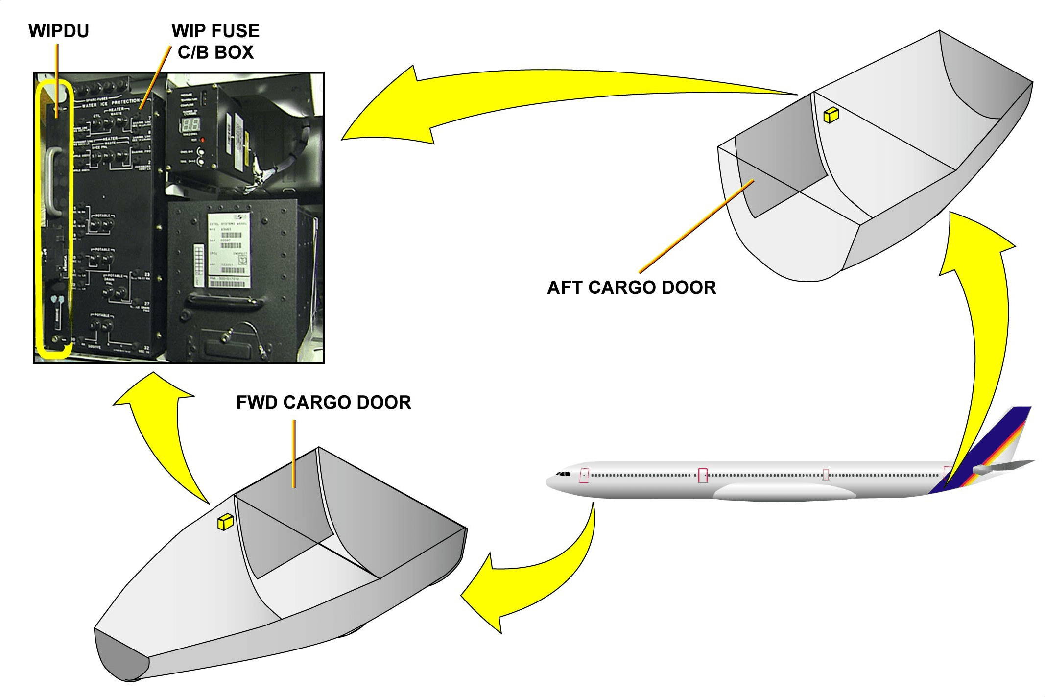
There are two WIPDUs by A/C: one is located in the avionic bay, the other in the aft cargo compartment. As the AMM procedure is the same for the FWD WIPDU setting and the aft WIPDU setting, the FWD WIPDU procedure is chosen for example.
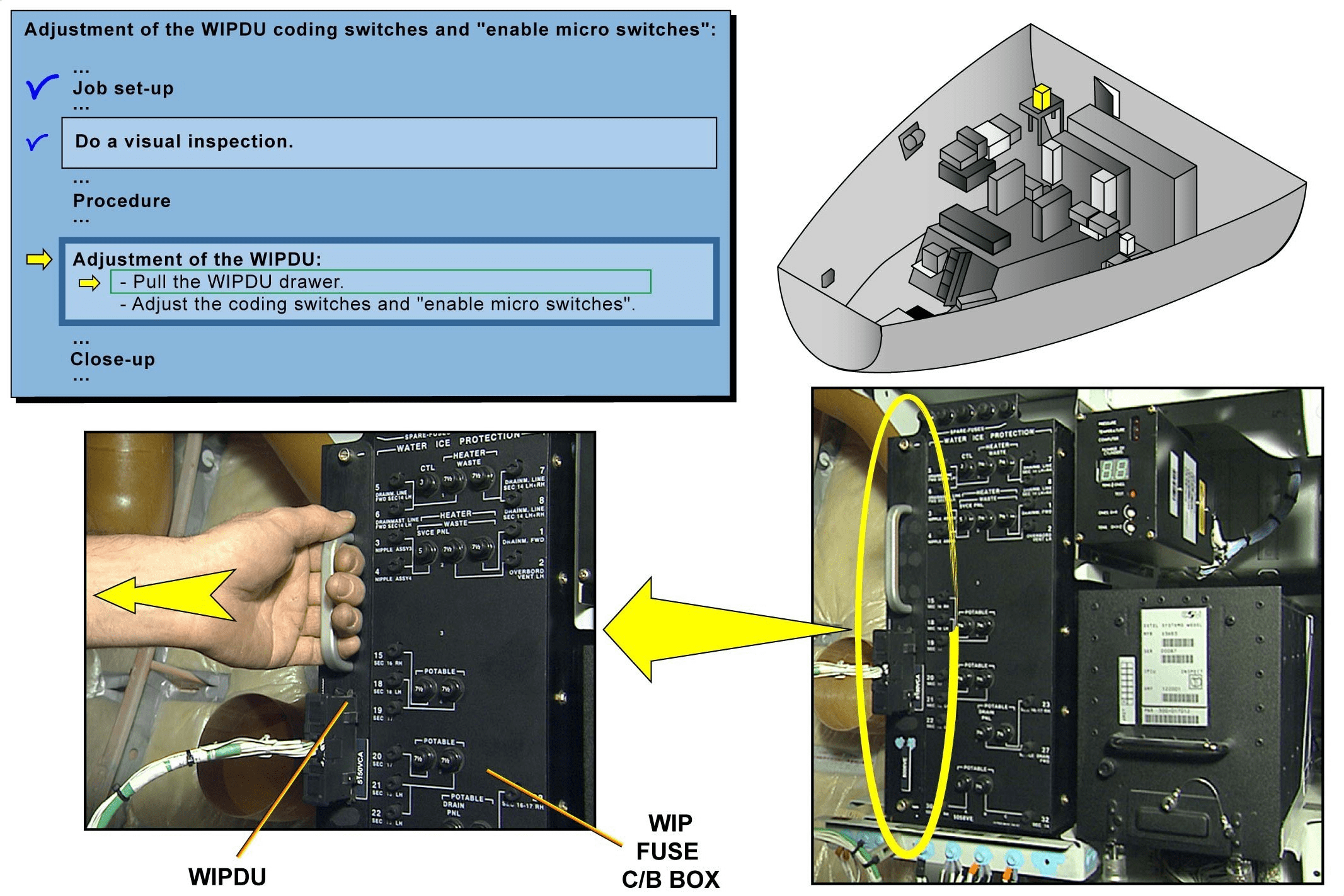
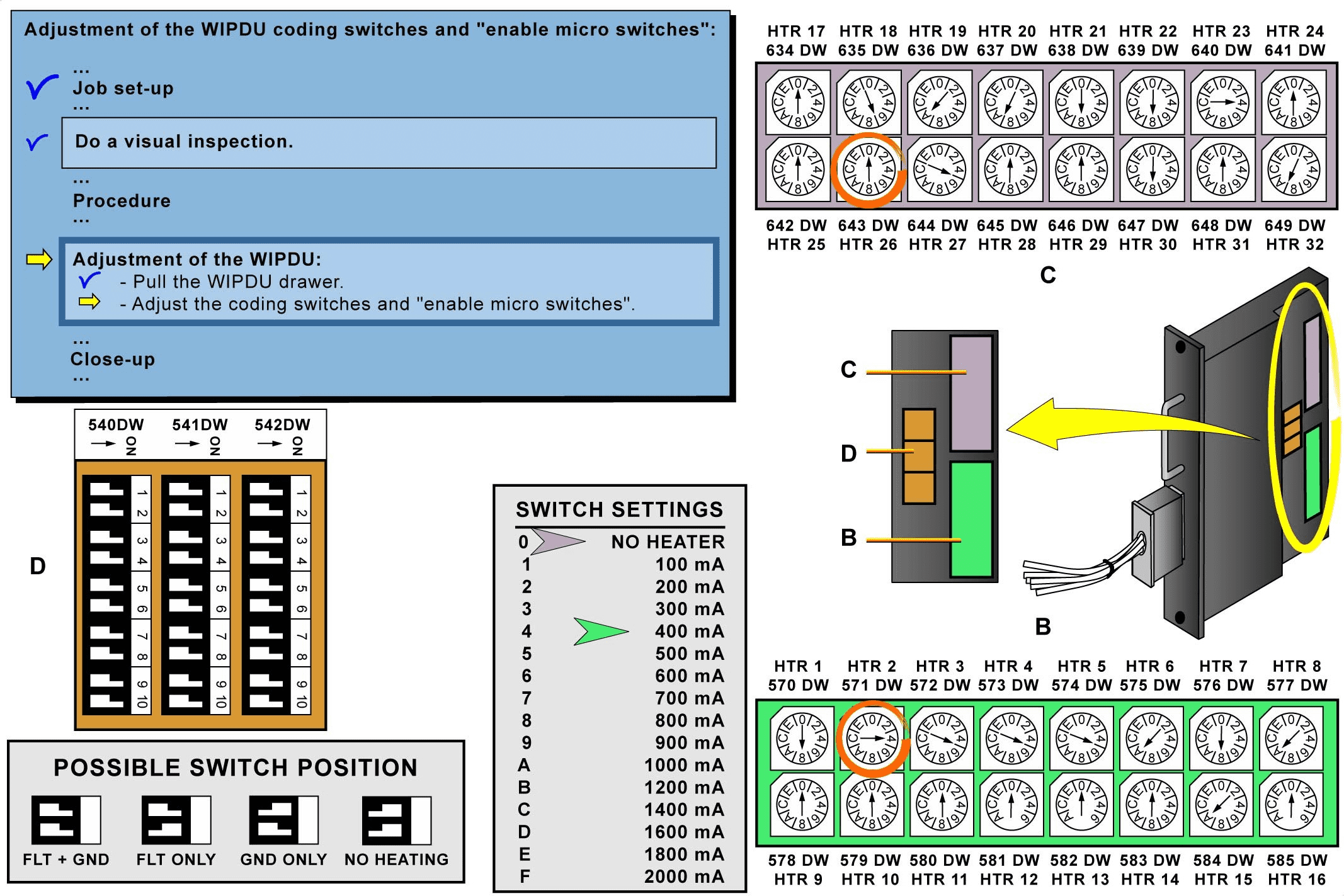
Do a visual inspection of the component interface and the adjacent area. The WIPDU is a removable Printed Circuit Board (PCB) fitted next to the Water Ice Protection fuse C/B box (WIP fuse C/B box). Pull the WIPDU after screws removal. Set the coding switches and “enable micro switches” according to the A/C heating circuits configuration and heating requirements.
NOTE: The displayed values are chosen for example. Each position of the coding switch corresponds to an intensity value. Install the WIPDU next to the WIP fuse C/B box and make sure the area is clean.
介绍
本模块描述了一个基本勤务程序。该任务涉及在更换部件后调整水冰保护数据单元(WIPDU)编码开关和 “启用微动开关”。
完成这项任务是为了将WIDPU为飞机加热电路配置的功能。
调整 WIPDU 编码开关和 “启用微动开关”
飞机有两个 WIPDU:一个位于航空电子设备舱,另一个位于机尾货舱。由于前后WIPDU设置的AMM程序相同,因此选择前后WIPDU程序为例。
对部件接口和邻近区域进行目视检查。WIPDU 是一块可拆卸的印刷电路板 (PCB),安装在水冰保护保险丝 C/B 盒(WIP 保险丝 C/B 盒)旁边。卸下螺丝后拉出 WIPDU。根据飞机加热电路配置和加热要求设置编码开关和 “启用微动开关”。
注意:所显示的数值只是举例说明。编码开关的每个位置对应一个强度值。将 WIPDU 安装在 WIP 熔断器 C/B 盒旁边,并确保该区域清洁。