电连接器的修理REPAIR OF ELECTRICAL CONNECTORS
1.INTRODUCTION 介绍
A.The following information is based on Boeing process specification BAC 5162 for assembly of electrical connectors. Several supplementary specifications supply additional information about specific connectors.
以下信息基于波音公司用于装配电气连接器的 工艺规范BAC 5162 。一些补充规范提供了有关特定连接器的更多信息
B.This information is intended to be general in nature. It does not necessarily cover all situations or
specific installations, but is to be used as a guide in establishing minimum standards for assembly of electrical connectors.
本信息具有通用性。它不一定涵盖所有情况或特定安装,但可作为制定电气连接器装配最低标准的指南。
C.Refer to SOPM 20-00-00 for a list of all the vendor names and addresses.
所有供应商的名称和地址清单,请参阅 SOPM 20-00-00。
2.DEFINITIONS OF TERMS 术语定义
A.Adapter Ring – An adapter which screws onto the threaded portion of some connectors when a potting mold is used. It supports potting mold and provides a bearing surface for coupling ring to physically disengage mating parts when the coupling ring is loosened.
适配器环 – 当使用灌封模具时,拧在某些连接器螺纹部分的适配器。它支撑灌封模具,并为连接环提供一个支承面,以便在松开连接环时使配合零件物理脱离。
B.Cable Clamp – The clamp at the rear of a connector endbell or a separate clamp adapter that screws onto the endbell. The cable clamp grips the wire bundle, providing strain relief to connector terminations.
电缆夹 – 连接器端环后部的夹子,或用螺丝固定在端环上的单独夹子适配器。电缆夹可夹住线束,为连接器终端提供应力消除。
C.Clocking – A term used to describe the assembly of angle type plug connectors to set a desired direction of “takeoff” for the wire bundle relative to the polarizing keyway (Figure 1).
时钟 – 用于描述角型插头连接器的装配,以设定线束相对于K键槽的期望的 “takeoff “方向(图 1)。
D.Connector – A mechanical device used to interconnect wiring in an electrical circuit, providing a manual disconnect at electrical equipment or other points determined by circuit design. The interconnection consists of an engaged “plug” and “receptacle” connector.
连接器 – 一种机械装置,用于互连电路中的线路,在电气设备或电路设计确定的其他点提供手动断开。互连装置由啮合的 “插头 “和 “插座 “连接器组成。
E.Endbell – An outside case which attaches to the connector shell and covers the terminations and rear end of connector.
端环 – 连接到连接器外壳的外部外壳,覆盖连接器的终端和后端。
F.Grommet – A compressible insulator, used with environment resisting connectors, which provides environmental sealing at the rear of the connector and supports individual wires.
扣眼 – 一种可压缩绝缘体,与耐环境连接器一起使用,在连接器后部提供环境密封,并支撑单根导线。
G.Grommet Follower – A sleeve which compresses the grommet in the assembled connector.
扣眼随动件 – 一种套管,用于将扣眼压入装配好的连接器中。
H.Insert – An insulator which holds the connector contacts in their proper arrangement and electrically insulates them from each other and the shell.
插件 – 一种绝缘体,用于将连接器插针固定在适当的位置,并使插针与外壳相互绝缘。
I.Pin – A male contact. It is normally connected to side of a circuit that is “dead” when plug and receptacle are disengaged.
插针 – 一个公连接插针。通常连接到插头和插座脱开时 “断开 “的电路一侧。
J.Plug – The connector which mates with a receptacle in the engaged assembly and is normally removable from the assembly after disengagement. A plug may have either pin or socket contacts.
插头 – 与啮合组件中的插座相连接的连接器,通常可在脱离后从组件上取下。插头可以有插针或插座插针
K.Polarization – The proper positioning of a plug with its receptacle by means of mating key and keyways, guide pins and sockets, pin and socket jack screws, or shell configuration.
极化 – 通过配合键和键槽、导向插针和插座、插针和插座插孔螺钉或外壳构型,使插头与插座正确定位。
L.Positioning – A term which refers to connector insert position relative to key or keyway in the shell. Standard positions are established as “normal” and alternate positions are indicated by letters or numbers.
定位(Positioning)–指相对于外壳上的键或键槽的连接器插入位置。标准位置被确定为 “正常 “位置,备用位置用字母或数字表示。
M.Receptacle – The connector which receives the mating “plug” in the engaged assembly. The receptacle is usually wall or box mounted, but may be a floating (unmounted) connector. A receptacle may have either pin or socket contacts.
插座 – 在啮合组件中接收配对 “插头 “的连接器。插座通常安装在墙壁或盒子上,但也可能是浮动(未安装)连接器。插座可以有插针或插座插针。
N.Shell – The outside case of a connector into which inserts and contacts are assembled.
外壳(shell)- 连接器的外壳,插入件和插针装配在其中。
O.Socket – A female contact. It is normally connected to the side of a circuit that is “live” when a plug and receptacle are disengaged.
孔针 – 母连接插针。当插头和插座脱开时,它通常连接到电路中 “带电 “的一侧。
P.Spare Wire Stub – A length of insulated wire attached to a contact in a potted connector with its opposite end protruding from the connector and unattached. The spare wire stub is provided to allow later modification to connector wiring by splicing to the spare wire stub without replacement of the potting material or connector.
备用线桩 – 连接到浇注式连接器插针上的一段绝缘导线,其另一端从连接器中伸出且未连接。提供备用线桩是为了日后修改连接器接线时,可将接线接在备用线桩上,而无需更换灌封材料或连接器。
Q.Sealing Rod – Tapered plastic rod used to fill holes through unwired contacts.
密封杆 – 锥形塑料杆,用于填充未接线插针的孔洞。

3.GENERAL REPAIR REQUIREMENTS 通用修理要求
A.Attaching Wires to Solderless Contacts
将导线连接到无焊插针
(1)Attach wires to solderless connector contacts in accordance with the following:
按照以下方法将导线连接到无焊料连接器的插针上:
(a)For some connectors with separable grommets or rear inserts, it may be desirable to insert wires through the insert or grommet holes prior to attaching contacts. Use this method in connectors with separate grommets when contacts have rugged or sharp protrusions which could damage the grommet if inserted through it.
对于某些带有可分离扣眼或后嵌件的连接器,最好在连接插针之前将导线穿过嵌件或扣眼孔。如果插针上有凹凸不平或尖锐的突起物,如果插入可能会损坏扣眼,则在带有独立扣眼的连接器中使用此方法。
(b)Insert wire conductor into contact barrel until wire is visible in the inspection hole.Exercise care to ensure that all conductor strands are inserted in the conductor crimp barrel.
将导线插入插针筒内,直至检查孔内可见导线。小心操作,确保所有导线都插入导线压接管。
(c)Bottom wire insulation in the insulation barrel of insulation gripping, or supporting contacts, as shown in Figure 2.
如图 2 所示,将导线绝缘层置于绝缘夹持或支撑插针的绝缘管中。
(d)Butt wire insulation against end of contact in noninsulation supporting contacts as shown in Figure 3. The maximum allowable gap between contact and wire insulation is 1/16 inch.
如图 3 所示,在非绝缘支撑插针中,将导线绝缘对接到插针端部。插针与导线绝缘层之间的最大允许间隙为 1/16 英寸。
(e)Crimp contacts with tools specified for the particular connector being assembled.
使用为装配特定连接器规定的工具压接插针。
(f)When crimping size 22 wire in a size 16 contact, strip wire to provide doubling back of conductor per Figure4. The conductor must be visible through inspection hole of contact. The cut end of folded back conductor must be visible but must not extend 1/32 inch beyond the back edge of contact crimp barrel (Figure4).
将规格 22 的导线压接在规格 16 的插针上时,应按照图 4 剥去导线,使导线加倍。通过插针的检查孔必须能看到导体。折回导体的切端必须可见,但不得超出插针压接筒后缘 1/32 英寸(图 4)。
B.Installing Solderless Contacts in Connectors
在连接器中安装无焊接插针
(1)Assemble solderless contacts in connectors according to Paragraph4., Paragraph 5. or Paragraph 6. and the following:
根据第 4.段、第 5.段或第 6.段以及以下内容组装连接器中的无焊插针:
CAUTION:DO NOT USE INSERTION TOOLS THAT HAVE BENT, SPREAD, FLARED, OR OTHERWISE DAMAGED INSERTION BITS OR TOOLS WITH SHARP EDGES.
注意:切勿使用弯曲、散开、外扩或损坏的插入工具或带有锋利边缘的工具。
(a)Insert contacts into resilient inserts of solderless contact connectors using appropriate insertion tool for specific contact-connector series, where applicable.
使用适用于特定插针连接器系列的适当插入工具,将插针插入无焊接插针连接器的弹性插件中。
1)Exercise care to properly grip or hold contacts in insertion tool since damage to contact, connector or tool may result from improper use. Avoid scraping wire insulation behind contact with insertion tool.
由于使用不当可能会损坏插针、连接器或工具,因此要小心正确地握住或固定插入工具中的插针。避免使用插入工具刮伤插针后面的导线绝缘层。
2)Insert contacts into a fully seated position in connector insert. When inserting contacts through a connector grommet, exercise care to avoid an abrupt insertion which does not allow sufficient time for grommet material to flow or stretch around contact and insertion tool. Always insert contacts straight and aligned with contact hole. Where lubrication is required to facilitate contact insertion through grommet, use a light application of alcohol.
将插针完全插入连接器插件。在将插针插入连接器扣眼时,应注意避免突然插入,以免扣眼材料没有足够的时间在插针和插入工具周围流动或伸展。应始终笔直插入插针,并与插针孔对齐。如果需要润滑以方便插针插入扣眼,可使用少量酒精。
NOTE:Lubricate only with alcohol when grommet is made of silicone or neoprene rubber.
注:当扣眼由硅橡胶或氯丁橡胶制成时,只能用酒精润滑。
CAUTION:DO NOT JERK ON WIRE OR INDENT WIRE INSULATION WITH FINGERNAILS.
注意:不要用手抓导线或用指甲压导线绝缘层。
(b)Check for proper seating of contact by grasping wire between thumb and forefinger and pulling slowly until thumb and forefinger slip on wire.
用拇指和食指夹住导线,慢慢拉动,直到拇指和食指在导线上滑动,检查插针是否正确就位。
C.Completing Connector Assembly
完成连接器组装
(1)General Requirements
通用要求
(a)Exercise care and minimize handling of connectors and wiring at all times to reduce possibility of connector damage and to avoid bend fatigue and breakage of wire conductors. Wire with damaged insulation must be rejected.
在任何时候都要小心谨慎,尽量减少对连接器和导线的操作,以降低连接器损坏的可能性,避免导线导体弯曲疲劳和断裂。必须报废绝缘层损坏的导线。
(b)Connectors internally contaminated with metal particles, water, dirt, grease, oil, carbon, adhesives, etc., are unacceptable.
内部被金属颗粒、水、灰尘、油脂、油、碳、粘合剂等污染的连接器不可接受。
(c)Connectors with bent or corroded contacts are unacceptable. Straightening of bent connector contacts is not permissible; however, correction of slight mating misalignment may be made when acceptable to Quality Control. Tarnished finish on silver, gold or rhodium plated contacts is not cause for rejection.
接点弯曲或腐蚀的连接器不可接受。不允许将弯曲的连接器插针拉直;但在质量控制可接受的情况下,可以纠正轻微的配接错位。镀银、镀金或镀铑插针上的污点不能作为报废原因。


4.PROTECTION OF CONNECTORS 连接器的保护
A.Every effort must be made to protect connectors from mechanical damage or contamination from foreign matter. Requirements for accomplishing this are as follows:
必须尽一切努力保护连接器免受机械损坏或异物污染。具体要求如下:
(1)Use standard snug fitting plastic dust caps to protect uncoupled ends of connectors against mechanical damage and contamination, except when necessary to work directly upon them.
使用标准的紧固塑料防尘盖保护连接器的未连接端,防止机械损坏和污染,除非需要直接在连接器上工作。
NOTE: For Electrostatic Discharge Sensitive (ESDS) connectors, a static shielding bag is not required if a conductive dust cap, connector cover or antistatic tape is used over theexposed connector.
注:对于静电放电敏感 (ESDS) 连接器,如果在暴露的连接器上使用导电防尘帽、连接器盖或防静电胶带,则不需要静电屏蔽袋。
(2)Protect connectors from contamination by falling or flying metal particles, water, dirt, grease, oil, carbon, etc., using polyethylene (or equivalent) bags. Use bags made of 0.006 to 0.012 inch thick material. All unsealed connectors (unpotted or without sealing grommet), whether coupled or uncoupled, require protection if exposure to contamination is expected, or can occur.
使用聚乙烯袋(或同等材料)保护连接器,防止金属颗粒、水、灰尘、油脂、碳等掉落或飞溅到连接器上。使用 0.006 至 0.012 英寸厚的材料制成的袋子。所有未密封的连接器(未浇注或无密封扣眼),无论是否耦合,如果预计会或可能会受到污染,都需要加以保护。
NOTE: If it is physically impossible to enclose connector in a bag, coverage may be provided by splitting bags and tying them in place.
注:如果实际上不可能将连接器装入袋中,可将袋子拆开并绑扎到位,以提供保护。
(3)Protect uninstalled connectors and installed uncoupled connectors by stowing or storing in a manner where contaminants will not fall or drain into protective cover.
保护未安装的连接器和已安装的未耦合连接器,方法是堆放或存放在污染物不会掉落或流入保护罩的地方。
5.SOLDERING WIRES TO SOLDER TYPE CONTACTS 将导线焊接到焊接型插针上
A.Soldering Connections
焊接连接器
(1) Place connector and wire bundle in an assembly holding fixture, when practical, during soldering operation. For soldering miniature connectors which have nylon inserts, engage connector with appropriate mating connector and secure in holding fixture.
在可行的情况下,在焊接操作过程中将连接器和线束放在装配夹具中。在焊接有尼龙嵌件的微型连接器时,将连接器与适当的配对连接器啮合并固定在固定装置中。
(2) Solder conductors to contact solder cups per SOPM 20-12-01.
按照 SOPM 20-12-01 将导体焊接到接触焊杯上。
(3) Where thermocouple contacts are removed from connectors for assembly, check for proper contact coding per Table 1 to make sure contacts are attached to correct thermocouple wires and replaced in correct insert location.
从连接器上拆下热电偶插针进行组装时,按表 1 检查插针编码是否正确,以确保插针连接到正确的热电偶导线上,并将插针替换到正确的插入位置。
B.Adapting Oversize Wire to Solder Cup
将超长导线连接到焊杯上
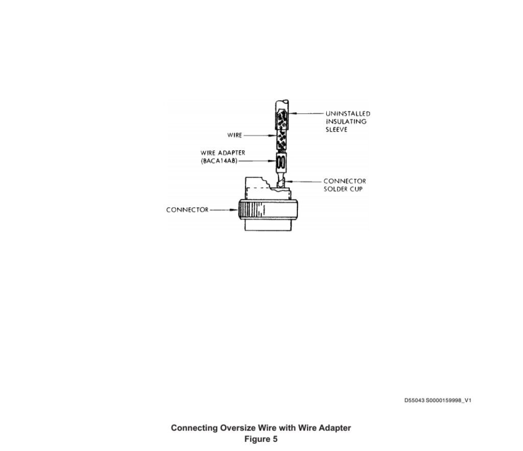
(1)Attach oversize wire to connector solder cups using BACA14AB wire adapters only when required by overhaul manual. Assemble adapters in accordance with the following:
仅在大修手册要求时,使用 BACA14AB 导线适配器将超大尺寸导线连接到连接器焊杯上。按照以下要求组装适配器:
(a)Provide a snug-fitting insulating sleeve for crimped assembly per Paragraph 7., and slide back on wire. The sleeve length must be such that it will cover finished termination and extend 5/8 ± 1/8 inch beyond the end of crimped adapter barrel on the finished termination. Omit sleeve if connector is to be potted.
根据第 7 段为压接装配提供一个紧贴的绝缘套管,并滑回到导线上。套管长度必须能够覆盖完成的终端,并超出完成终端上压接的适配器桶端 5/8 ± 1/8 英寸。如果连接器要浇注,则省略套管。
(b)Bottom wire conductor in adapter barrel and crimp adapter using tooling indicated in Table 2.
使用表 2 所示的工具,将导线导体底端装入适配器套筒并压接适配器。
(c)Solder the adapter pin in connectorsolder cup per SOPM 20-12-01 (Figure 5).
按照 SOPM 20-12-01 (图 5)将适配器插针焊接到连接器夹杯中。
(d)Butt sleeve against insert and secure in place per Paragraph 7..
按照第 7 段将套管对准插入件并固定到位。
(2)Adaptation of an oversize wire to a connector solder cup may be made using a BACC34B copper sleeve only when required by Overhaul Manual or when BACA14AB wire adapters are not available in required size. Solder and insulate sleeves as required for BACA14AB adapters, above, except as follows:
只有在大修手册要求或没有所需尺寸的 BACA14AB 导线适配器时,才可以使用 BACC34B 铜套将超大尺寸导线适配到连接器焊杯上。按照上述 BACA14AB 转换接头的要求焊接和安装绝缘套管,但以下情况除外:

(a) Make two loops and an overhand tie at the base of the solder cup with tying material per BAC5157. This will be used as a gasket in the next step.
按照 BAC5157 用绑带材料在焊杯底部做两个环和一个过手绑带。这将在下一步中用作垫圈。
(b) Put a tight-fitting BACC34B sleeve over the solder cup and push it down against the tie you made in step (a).
在焊杯上套上一个紧贴的 BACC34B 套管,并将其向下压,顶住在步骤 (a) 中制作的绑带。
(c) Melt Type R rosin core solder between the sleeve and the solder cup. Fill the cup slightly over the top, then let the solder become solid.
在套管和焊杯之间熔化 R 型松香芯焊料。将焊杯稍微填满,然后让焊料凝固。
(d) Put the wire into the copper sleeve until it pushes on the hardened solder. Heat the wire and the sleeve to the flow point of the solder, push the wire down to the bottom, and then remove the heat. Hold the assembly firmly in position until the solder becomes solid again (Figure 6).
将导线放入铜套管,直到导线推到硬化的焊料上。将导线和套管加热到焊料的流动点,将导线推到底,然后移开热量。将组件牢牢固定在原位,直到焊料再次变硬(图 6)。
6. QUALITY CONTROL REQUIREMENTS 质量控制要求
A. During assembly and before you attach endbells or install potting compound, make sure the inserts, contacts, grommets, and wires are clean and have no defects.
在组装过程中,以及在安装端环或灌封胶之前,确保插件、插针、扣眼和导线清洁无瑕。
B. Be sure that crimping tools, stripping tools and insertion-extraction assembly tools are certified.
确保压接工具、剥线工具和插入-拔出装配工具经过认证。
C. Make sure that stripping tools do not damage conductors. Refer to Paragraph 8.E. for details.
确保剥线工具不会损坏导体。详情请参阅第 8.E 段。
D. Make sure the contacts are correctly crimped, and that you can see the conductors through the inspection hole of contact wire barrel.
确保插针压接正确,并能通过插针线筒的检查孔看到导体。
E. Reject connectors if there are cuts, cracks, gouges, chips, or tears on the front or the rear face of resilient connector grommets.
如果弹性连接器扣环的正面或背面有切口、裂纹、刨花、缺口或撕裂,则拒绝接受连接器。
F. For MIL-C-26500 (BACC45F) connectors, you can make a check of the completed connector with the applicable ST8756 alignment gage if you think the contacts are not aligned.
对于 MIL-C-26500 (BACC45F) 连接器,如果您认为插针未对齐,可以使用适用的 ST8756 对齐规检查已完成的连接器。

7. INSULATING TERMINATIONS 绝缘端子
A. Use an insulating sleeve to cover contacts installed in connectors that do not have connector sealing grommets or a rear insulator.
使用绝缘套管覆盖安装在没有连接器密封扣环或后绝缘体的连接器上的插针。
(1) Preferred Method — Installation of heat shrinkable tubing
首选方法 — 安装热缩套管
(a) Use a sleeve size that fits easily over the termination before it is shrunk, and fits tightly and does not move after it is shrunk.
使用的套管尺寸在收缩前应易于套在终端上,收缩后应紧密贴合且不会移动。
(b) Make the sleeve extend over the conductor insulation 0.37-0.63 inch. Make the gap between the sleeve and the insert face less than 0.06 inch. Install the sleeve as near the insert face as possible.
使套管伸出导体绝缘层 0.37-0.63 英寸。使套管与插入面之间的间隙小于 0.06 英寸。安装套管时尽量靠近插入面。
(c) Shrink the sleeve in position (SOPM 20-11-03).
将套管收缩到位(SOPM 20-11-03)。
(2) Optional Method — Installation of non-shrinkable sleeve
可选方法 — 安装非收缩套管
(a) Use the smallest size of sleeve that fits over the termination.
使用适合终端的最小尺寸的套管。
(b) Install the sleeves with one end against the connector insert and the other end 0.37-0.63 inch out from the contact.
安装套管时,一端靠在连接器插件上,另一端距插针 0.37-0.63 英寸。
(c) Tie the sleeves in position with a wire bundle tie. Tie the sleeve to the wire, or put the tie on the wire directly behind the sleeve. Make sure the sleeve does not slip over the tie. Sleeves on a group of up to 7 adjacent contacts can be attached by one tie on the wires behind the sleeves. Be sure the installed ties do not put stress on the wire connections.
用线束扎带将套管绑好。将套管绑在导线上,或将扎带直接绑在套管后面的导线上。确保套管不会从绑带上滑落。最多可将 7 个相邻插针的套管用一条扎带绑在套管后面的导线上。确保安装的扎带不会对导线连接造成压力。
8. PREPARATION OF WIRES 导线的准备
A. If possible, use an assembly holding fixture which will hold both wires and connector for the wire preparation and soldering operations.
如果可能,使用一个装配夹具,该夹具可在导线准备和焊接操作中同时夹住导线和连接器。
B. Lay the wires in the bundle support of the holding fixture in the positions in which they terminate. Move the individual wires to their contact locations and cut them to the correct length for assembly.
将导线按其端接位置放置在夹具的线束支架上。将单根导线移至其接触位置,并剪切至正确长度以便组装。
C. For potted assembly of Teflon insulated wire, etch the wires or install sleeves on them, unless the wire is pretreated for potting.
对于聚四氟乙烯绝缘导线的灌封组装,除非导线经过灌封预处理,否则应蚀刻导线或在导线上安装套管。
D. Strip wire insulation with a correctly-adjusted stripping tool. Be sure not to cut or nick the conductor strands. Small scrapes are permitted on wire strands, and on tinned or plated copper wires which makes some bare copper areas. Wire grips of stripping tools must not cut, extrude or otherwise damage wire insulation, but small dents or impressions are acceptable.
使用正确调整的剥线工具剥去导线绝缘层。确保不要切断或划伤导线。允许在导线绞合处以及镀锡或镀层铜线上的一些裸铜区域进行小刮擦。剥线工具的线握不得切断、挤压或以其他方式损坏导线绝缘层,但可留下小凹痕或印记。
E. Strip the wire to the length for the specified contact and terminating method. For assembly in solder type contacts, include sufficient length for an inspection gap between the wire insulation and the contact solder cup (SOPM 20-12-01).
将导线剥至规定的插针和端接方法所需的长度。对于焊接式插针的装配,应在导线绝缘层和插针焊杯之间留出足够的检查间隙(SOPM 20-12-01)。
F. If the wires are too small for the grommets of environmentally sealed grommets, increase the diameter of their insulation with layers of heat shrinkable sleeving. Refer to BAC5162, or Standard Wiring Practices Manual 20-60-08, for details.
如果导线太小,无法穿过环保密封扣环的扣眼,可使用多层热收缩套管增加其绝缘层的直径。详情请参阅 BAC5162 或SWPM:20-60-08。(SWPM:标准线路施工手册》)
9. SPARE WIRE STUBS 备用线桩
A. Make the spare wire stubs from wire of the highest temperature rating used in the bundle and of the largest size that will fit in the contact. Identify the wire stubs.
用线束中使用的最高温度额定值的导线制作备用线桩,其尺寸应是适合插针的最大尺寸。。标明线桩。
B. Give protection to the ends of spare wire stubs with flexible sleeves or shrinkable sleeves or end caps. Make spare wire stubs in groups approximately 5 to 7 inches long, and stagger the groups of stubs as necessary to prevent excessive bundle enlargement. Do not put the ends of unused or spare wires in conduit.
用柔性套管或收缩套管或端盖保护备用线桩的端部。将备用线桩分成大约 5 至 7 英寸长的几组,并根据需要将各组线桩错开,以防止线束过度扩大。不要将未使用或备用导线的末端放入导管中。
C. Attach the spare wire stubs within or on the surface of the wire bundle. Put one bundle tie within 0.75 inch from the end of each group of spare wire stubs, and put one bundle tie midway between the connector and the end of the shortest group of stubs.
在线束内或线束表面安装备用线桩。在距离每组备用线桩末端 0.75 英寸的范围内打上一条捆扎带,并在连接器和最短一组线桩末端的中间打上一条捆扎带。
10. TIGHTENING GROMMET NUTS (Amphenol Connectors Only)拧紧定位螺母(仅Amphenol连接器)
A. On connectors with ferrules, make sure the ferrule lands are down in the shell slots, and that the ferrule insert and grommet nut are aligned. Tighten the grommet nut slightly more than hand tight.
对于带卡套的连接器,确保卡套底面位于外壳槽中,卡套插入件和扣眼螺母对齐。拧紧扣眼螺母时要比用手拧紧稍多一些。
11. REMOVING SEALING ROD FROM CONNECTOR 从连接器上卸下密封杆
A. Remove cable support (and grommet nut and ferrule of Amphenol connectors, if used).
卸下电缆支架(如果使用Amphenol连接器,则卸下扣眼螺母和卡套)。
B. Remove sealing rods as follows:
按如下步骤卸下密封杆:
(1) If a spare contact is not installed, hold the free end of the sealing rod with pliers and gently pull the rod away from the connector, along the axis of the grommet hole.
如果没有安装备用插针,用钳子夹住密封杆的自由端,沿着扣眼孔的轴线轻轻将密封杆拉离连接器。
(2) If a spare contact is installed with the sealing rod, remove the contact first, then remove the sealing rod.
如果备用插针与密封杆一起安装,则先卸下插针,然后卸下密封杆。
12. SECURING CONNECTOR PARTS 固定连接器零件
A. Connector endbells, assembly nuts, and cable clamp adapters must be correctly assembled and tightened. Do not tighten parts too much, or you could damage connector threads or parts.
必须正确组装和拧紧连接器端环、装配螺母和电缆夹适配器。不要将零件拧得太紧,否则可能会损坏连接器螺纹或零件。
B. On connectors which have standard threaded assembly nuts, endbells or separate cable clamps, tighten the parts by hand, then tighten slightly more (max. 1/8 turn) with tool ST2596G, ST2596C or AT508K (Aircraft Tools, Inc., V00784).
对于带有标准螺纹装配螺母、端环或单独电缆夹的连接器,用手拧紧零件,然后用工具 ST2596G、ST2596C 或 AT508K(Aircraft Tools, Inc., V00784)稍稍拧紧(最多 1/8 圈)。
C. On connectors with nuts, endbells or cable clamps to be lockwired, tighten these parts per par. B. above.
对于带有螺母、端环或电缆夹的连接器,要打保险丝。按上述B. 段的规定拧紧这些部件。
D. On connector endbells attached with set screws, tighten the set screws approximately an equal number of turns. Do not tighten the set screws too much. You could break the connector shell.
对于用固定螺钉连接的连接器端环,拧紧固定螺钉的圈数大致相等。不要将固定螺钉拧得太紧。否则会损坏连接器外壳。
E. Assemble connectors with angle type cable clamps in the clocking position called out by the overhaul instructions. See Figure 1 for example docking positions. Unless otherwise specified, the allowable clocking tolerance is ±1 hour (30°). If clocking is not specified, put the connector mating key or keyway at twelve o’clock. Put the angle type cable clamp at six o’clock.
使用角型电缆夹将连接器安装在大修说明要求的时钟位置。对接位置示例见图 1。除非另有规定的,允许的时钟公差为 ±1 小时(30°)。如果没有规定的时钟位置,则将连接器配合键或键槽置于十二点钟位置。将角型电缆夹放在六点钟方向。
F. Make checks for tightness of connector parts by hand and only in the direction that tightens the part. Make checks for tightness before you install the lockwire.
用手检查连接器零件的松紧度,并且只能按照拧紧零件的方向进行。在安装保险丝之前检查松紧度。
13. MATERIALS AND EQUIPMENT 材料和设备
A. Materials
材料
NOTE: Equivalent substitutes can be used. Also see the instructions for the specific connector.
注: 可使用同等替代品。另请参见特定连接器的说明。
(1) Sealing Rod 密封杆– Type I vinyl or Type IV Teflon in Type I, non-Skydrol areas. Use only Type IV Teflon in Type II and higher areas.
(2) Sleeving, non-shrinkable 非收缩套管– MIL-I-7444 or MIL-I-3190/6
(3) Alcohol, isopropyl (SOPM 20-60-01)
异丙醇
(4) Sleeving, heat-shrinkable 热缩套管– MIL-DTL-23053 or MIL-R-46846
B. Tools
工具
NOTE: Equivalent substitutes can be used.
注:可使用同等替代品。
(1) Insertion and Removal Tools — See the instructions for the specific connector.
插入和拆卸工具 — 参见特定连接器的说明。
(2) Crimp Tools and Locators — See the instructions for the specific connector.
压接工具和定位器 — 参见特定连接器的说明。
(3) Wire Stripping Tool — ST2346
剥线工具 — ST2346 14.
14. REPAIR OF MIL-C-26500 SOLDERLESS CONNECTORS (BACC45F( )) 修理 MI-C-26500 无焊接连接器(BACC45F( )
A. Connector Nomenclature (Figure 7)
连接器命名法(图 7)
NOTE: Early configurations could have ferrules, grommet nuts, load rings and noncaptive coupling rings. Screws supplied with early version connector cable clamps can be replaced with longer screws. For replacements, use screws of the same head and thread configuration as the old screws.
注:早期构型可能有卡套、扣眼螺母、负载环和非卡套连接环。可使用较长的螺钉替换早期版本连接器电缆夹提供的螺钉。更换时,请使用与旧螺钉相同头部和螺纹结构的螺钉。
B. Part Numbering of Connectors
连接器的件号
(1) BAC Part Number — See Figure 8
BAC 件号 — 见图 8
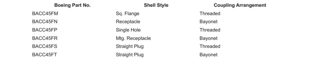
(2) Shell Style and Coupling Arrangements
外壳样式和耦合排列
C. Removing Contacts from Connector
从连接器上拆下插针
CAUTION :DO NOT ATTEMPT TO REMOVE GROMMETS FROM CONNECTORS, AS THEY ARE BONDED TO SHELL.
注意 :不要试图从连接器上拆下扣眼,因为它们与外壳粘接在一起。
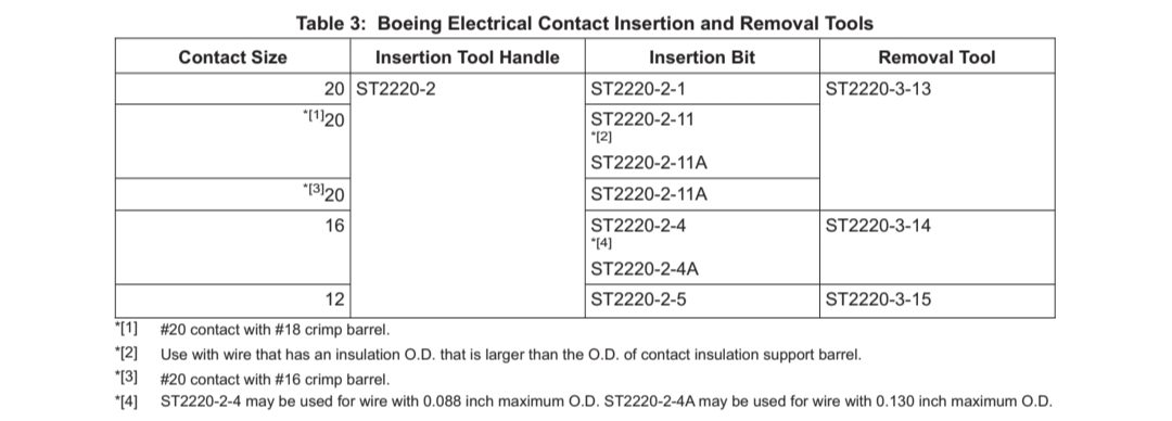
(1) Select correct contact removal tool from Table 3.
从表 3 中选择正确的插针拆除工具。
NOTE: Equivalent vendor tools may be used in place of above ST-tools.
注:可使用供应商提供的同等工具代替上述 ST 工具。
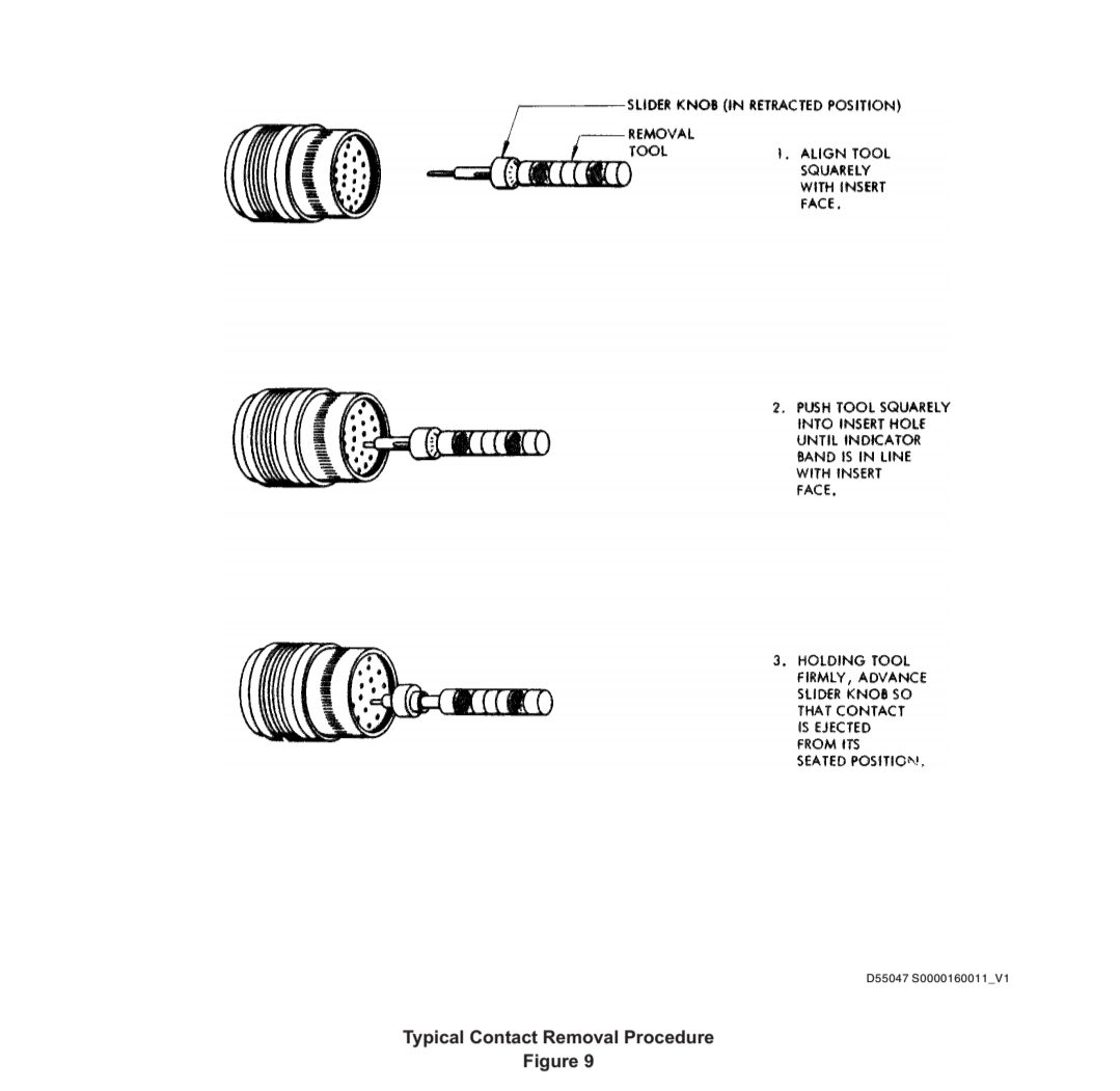
(2) Slide contact removal tool end over contact and into the insert hole. Insert tool until first mark on tool tip, for pin contacts, or until second mark, for socket contacts, coincides with insert face.
将插针拆卸工具的一端滑过插针,插入插入孔。对于销钉式插针,插入工具直至工具顶端的第一个标记与插入面重合;对于孔钉式插针,插入工具直至工具顶端的第二个标记与插入面重合。
CAUTION :RETENTION CLIPS MAY BE DAMAGED IF REMOVAL TOOL IS INSERTED FARTHER THAN SPECIFIED.
注意 :如果拆卸工具插入的距离超过规定的距离,可能会损坏固定夹。
(3) With removal tool held firmly in this position, rotate tool slightly to assure that it is properly seated in retention clip. Advance internal plunger so that contact is ejected from its seated position. See Figure 9 for contact removal procedure.
将拆卸工具牢牢固定在此位置,稍稍旋转工具以确保其正确插入固定夹。推进内部柱塞,使插针从其固定位置弹出。有关插针拆卸程序,请参见图 9。
CAUTION :TO MINIMIZE POSSIBLE GROMMET DAMAGE, REMOVE EACH CONTACT COMPLETELY ONE AT A TIME. DO NOT RELEASE SEVERAL CONTACTS WITH REMOVAL TOOL BEFORE COMPLETE REMOVAL FROM GROMMET. IF CONTACTS ARE DIFFICULT TO REMOVE, CHECK REMOVAL TOOL TIP FOR PROPER TAPER.
注意 :为尽量减少可能对扣眼造成的损坏,请一次完全取下每个插针。在从扣眼上完全拆下之前,不要用拆卸工具松开多个插针。如果插针难以取下,检查拆卸工具的尖端是否有适当的锥度。
(4) The contact may then be pulled free of grommet with hand. Do not use pliers to remove contacts.
然后用手将插针从扣眼中拉出。不要用钳子取下插针。
D. Removing Wires From Solderless Contact
从无焊接插针上拆卸导线
(1) Cut wire at end of wire insulation, using wire cutters or similar tool.
使用剪线钳或类似工具在导线绝缘层末端剪断导线。
E. Installing Contacts on Wire
在导线上安装插针
(1) Strip wire 3/16 ± 1/32 inch for size 20 contacts, and 9/32 ± 1/32 inch for size 16 and 12 contacts, using stripping tool ST2346 or equivalent. If wire is too large to enter insulation support barrel of a size 20 contact, strip wire 9/32 ± 1/32 inch.
使用 ST2346 或同类剥线工具,对 20 号插针剥线 3/16 ± 1/32 英寸,对 16 号和 12 号插针剥线 9/32 ± 1/32 英寸。如果导线过大,无法进入 20 号插针的绝缘支撑筒,则将导线剥开 9/32 ± 1/32 英寸。
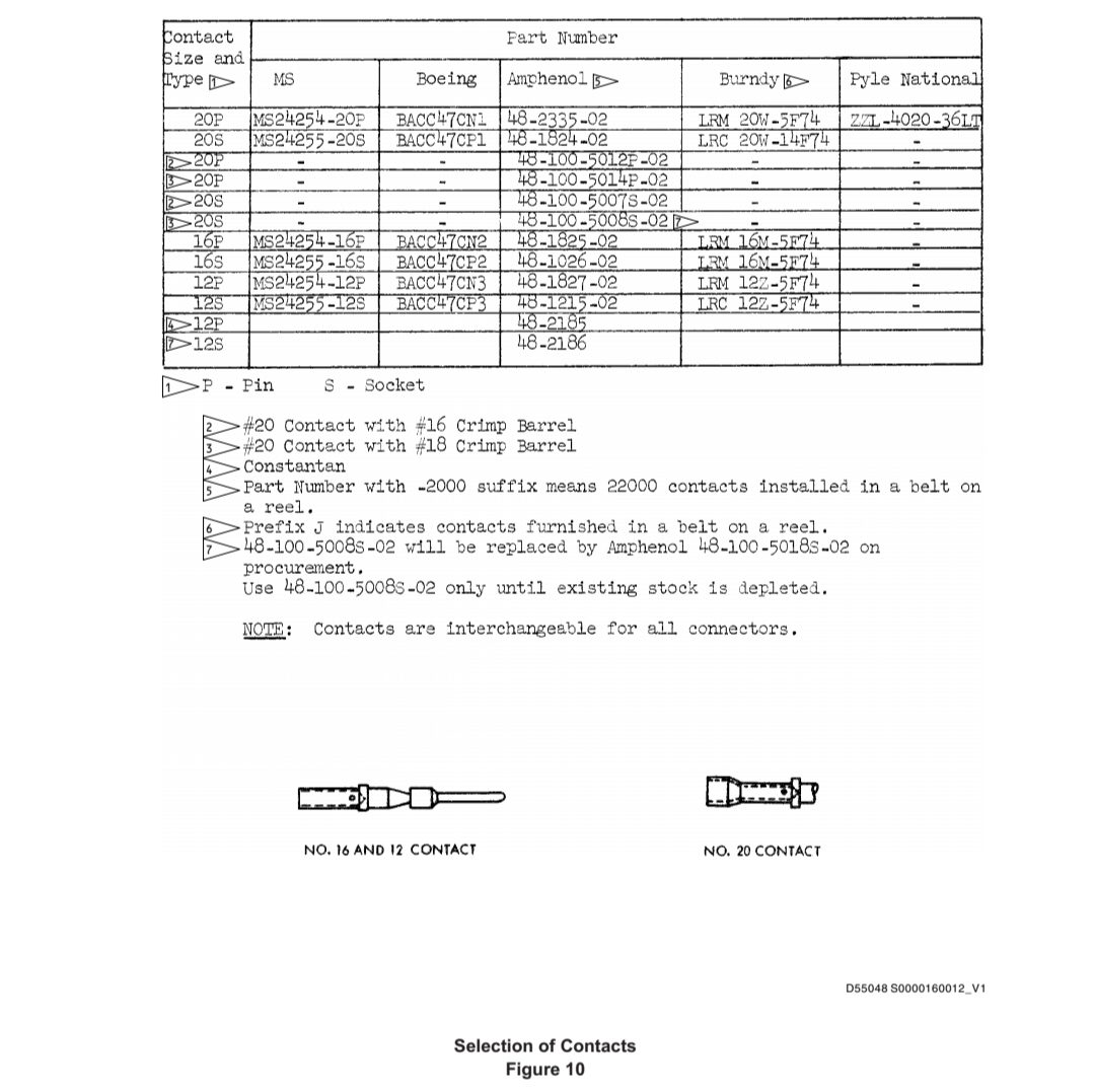
(2) Select correct contact per Figure 10.
根据图 10 选择正确的插针。
CAUTION :MAKE CERTAIN THAT PROPER CRIMP TOOL AND PROPER LOCATOR ARE USED.
注意 :确保使用正确的压接工具和正确的定位器。
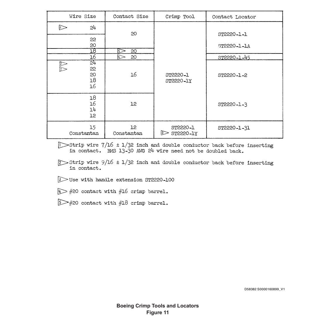
(3) Place contact in correct locator and crimp tool per Figure 11. Insert stripped end of wire in crimp barrel of contact, making certain all conductor strands enter barrel and that they are visible through inspection hole.
按照图 11 将插针放入正确的定位器和压接工具中。将剥线端插入插针的压接筒中,确保所有导体股均进入压接筒中,并可通过检查孔看到。
NOTE: As an alternate method, the wire may be placed in contact before inserting contact in crimp tool locator.
注:作为替代方法,可在将插针插入压接工具定位器之前将导线放入插针。
(4) With contact shoulder seated in locator, and wire bottomed in contact, close handles of crimp tool until ratchet releases. Remove contact wire assembly from crimp tool.
插针肩部插入定位器,导线底部插入插针,关闭压接工具的手柄,直到棘轮松开。从压接工具中取出插针-导线组件。
F. Inserting Contacts into Connector
将插针插入连接器
(1) With Amphenol connectors, when grommet nut and ferrule or cable support nut are used, slide these parts back over wire bundle before inserting contacts. With Pyle-National connectors, slide cable support nut back over wire bundle. This must be done to prevent damage to grommet during insertion.
对于 Amphenol 连接器,当使用扣眼螺母和卡套或电缆支撑螺母时,应在插入插针前将这些零件滑回到线束上。对于 Pyle-National 连接器,应将电缆支撑螺母滑回到线束上。必须这样做,以防止在插入过程中损坏扣环。
(2) Examine contacts for straightness per Paragraph 3.B.
根据第 3.B 段检查插针是否平直。
(3) Lubricate the rear face of the grommet per Paragraph 3.B. If more lubrication is necessary, you can use small amounts of Dow Corning DC 200 or Silastic RTV Thinner (BAC5162).
按照第 3.B 段润滑扣眼后端面。如果需要更多润滑,可使用少量 Dow Corning DC 200 或 Silastic RTV 稀释剂 (BAC5162)。
NOTE: Do not immerse connector or contact-wire assemblies in lubricant.
注: 不要将连接器或插针-导线组件浸入润滑剂中。
(a) Install sealing rod per Paragraph 14.G. and insert contact wire assemblies per Paragraph 14.F.(5) or Paragraph 14.F.(6) below.
按照第 14.G 段安装密封杆,并按照下文第 14.F.(5) 段或第 14.F.(6) 段插入插针-导线组件。
NOTE: All insert holes which are not fitted with a wired contact are required to be filled with sealing rod.
注:所有未安装接线插针的插入孔都必须填满密封杆。
(4) Select proper insertion tool per Table 3. Observe the following:
根据表 3 选择合适的插入工具。注意以下事项
(a) That correct connector parts and insertion tools are used.
使用正确的连接器零件和插入工具。
(b) That insertion bit is not bent, spread, flared or otherwise damaged.
插头没有弯曲、张开、外扩或其他损坏。
(c) That insertion bit edges that come into contact with connector insert are not sharp.
与连接器插件接触的插入位置边缘不锋利。
(d) On size 20 contacts, that the insertion tool tip is around insulation support barrel of contact, and not on rear edge.
对于 20 号插针,插入工具的尖端应在插针的绝缘支撑筒周围,而不是后边缘。
NOTE: Lubricate the tip of insertion tool, per Paragraph 3.B., before inserting contact-wire assemblies. Dow Corning DC-200 or “Silastic RTV Thinner” may be used if additional lubrication is required.
注: 在插入插针-导线组件之前,应根据第 3.B 段润滑插入工具的尖端。如果需要额外润滑,可使用Dow Corning DC-200 或 “Silastic RTV 稀释剂”。
(5) Insert contact-wire assemblies individually as follows:
按以下步骤逐个插入插针-导线组件:
(a) Grasp contact (socket or pin) with insertion tool tip by sliding contact into insertion tool tip end, as shown in Figure 12.
如图 12 所示,用插入工具尖端抓住插针(孔针或钉针),将插针滑入插入工具尖端端部。
(b) Guide contact-wire assembly carefully through proper grommet hole (Figure 12). Push tool straight in axially to grommet hole until contact is fully seated.
小心引导插针-导线组件穿过适当的扣眼孔 (图 12)。将工具沿轴向推入扣眼孔,直到插针完全就位。
(6) Preload all or several contacts in grommet and complete insertion as follows:
在扣眼中预装所有或几个插针,并按以下步骤完成插入:
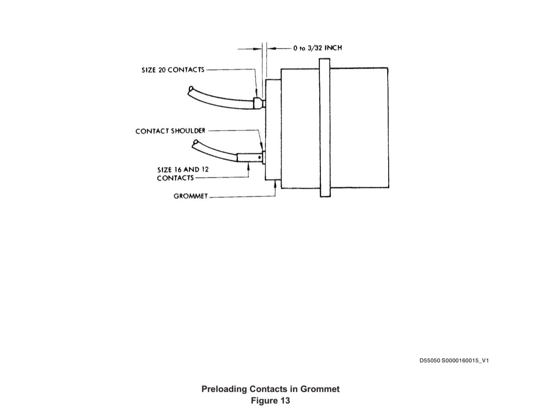
(a) Grasp contact-wire assembly with fingers and guide it carefully through proper grommet hole until contact insulation barrel of size 20 contact is flush to 3/32 inch from rear grommet surface. For size 16 and 12 contacts, shoulder of contact shall rest on rear surface of grommet (Figure 13).
用手指抓住插针-导线组件,小心地将其导入适当的扣眼孔中,直至 20 号插针的绝缘筒与扣眼后表面齐平至 3/32 英寸。对于 16 号和 12 号插针,插针肩部应靠在扣眼后表面上(图 13)。
(b) Hold connector in one hand and with other hand slide tip of insertion tool over end of contact-wire assembly and push tool straight in axially to grommet hole until contact is fully seated.
一只手握住连接器,另一只手将插入工具的顶端滑到插针-导线组件的末端,然后将工具沿轴向推入扣眼孔,直到插针完全就位。
CAUTION:KEEP CONTACT AND INSERTION TOOL ALIGNED AXIALLY TO GROMMET HOLE DURING INSERTION.
注意:在插入过程中,要保持插针和插入工具与扣眼孔的轴向对齐。
(7) A slight snap and increased resistance to further motion will be felt when contact seats.
插针就位时,会感觉到轻微的卡扣声,进一步移动的阻力会增加。
(8) Withdraw insertion tool carefully from insert.
小心地从插件中拔出插入工具。
CAUTION :DO NOT JERK ON WIRE OR INDENT WIRE INSULATION WITH FINGERNAILS.
注意 :不要在导线上抽动或用指甲压入导线绝缘层。
(9) Check for proper contact seating by grasping each wire between thumb and forefinger and pulling slowly until thumb and forefinger slip on wire.
用拇指和食指抓住每根导线,慢慢拉动,直到拇指和食指在导线上滑动,检查插针是否正确就位。
(10) If contact is not properly inserted, it must be removed per Paragraph 14.C. and reinserted as specified above.
如果插针没有正确插入,必须按照第 14.C 段的规定将其拆下,然后按照上 述规定的方法重新插入。
G. Sealing Unused Grommet Holes
密封未使用的扣眼孔
CAUTION :WHEN A CONNECTOR WITH A FERRULE IS USED, CHECK TO ENSURE THAT GROMMET NUT AND FERRULE ARE LOOSENED BEFORE SEALING RODS ARE INSTALLED.
注意 :当使用带卡套的连接器时,在安装密封杆之前,应检查确保扣眼螺母和卡套已松开。
(1) Use Type I vinyl or Type IV Teflon sealing rod in Type I, non-Skydrol areas.
在 I 类非 Skydrol 区域使用 I 类乙烯基或 IV 类聚四氟乙烯密封杆。
(a) Use only Type IV Teflon sealing rod in Type II and higher areas and in Skydrol areas.
在 II 型及以上区域和 Skydrol 区域只能使用 IV 型 Teflon 密封杆。
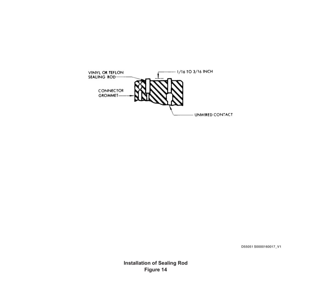
(2) Install vinyl or Teflon sealing rod per Table 4 and Figure 14.
按照表 4 和图 14 安装乙烯基或特氟龙密封杆。
CAUTION :DO NOT USE SCRATCHED OR DAMAGED SEALING ROD. DO NOT PUSH SEALING ROD ALL THE WAY INTO GROMMET HOLES.
注意 :不要使用有划痕或损坏的密封杆。不要将密封杆完全推入扣眼孔中。
(a) If spare contacts are installed in connector, bottom sealing rod against ends of spare contacts and trim rod so it extends 1/16 to 3/16 inch above grommet surface.
如果在连接器中安装了备用插针,则将密封杆底部对准备用插针的两端,并修整密封杆,使其超出扣眼表面 1/16 至 3/16 英寸。
(b) If spare contacts are not installed in connector, cut rod to length shown in Table 4 and install rod so it extends 1/16 to 3/16 inch above grommet surface.
如果连接器中未安装备用插针,则按表 4 中所示的长度切割密封杆并安装密封杆,使其超出扣眼表面 1/16 至 3/16 英寸。


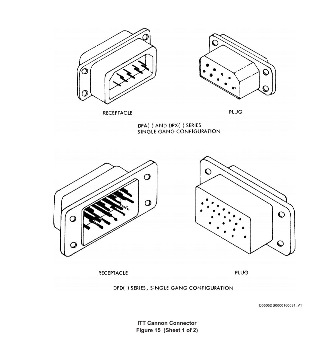
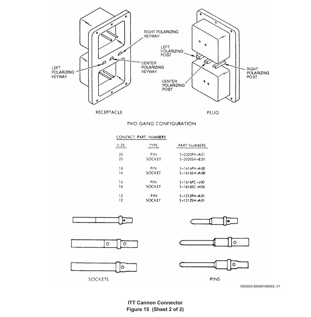
15. REPAIR OF ITT CANNON, DPA, DPD AND DPX (MA AND MB) SERIES SOLDERLESS 修理 ITT CANNON、DPA、DPD和DPX(MA和MB)系列无焊接件
A. Connector Nomenclature (See Figure 15).
连接器命名法(见图 15)。
B. Part Numbering of Connectors
连接器的件号
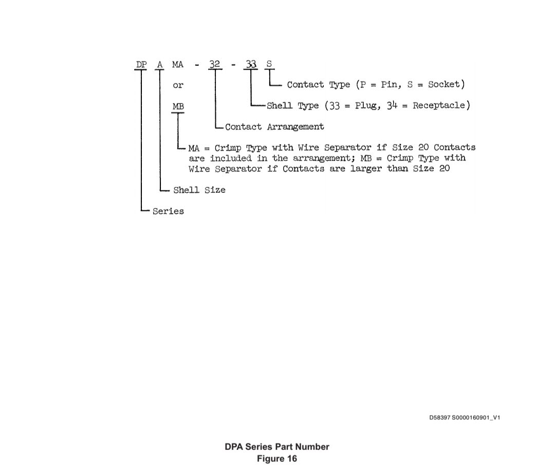
(1) Typical DPA Series Part Number (See Figure 16)
典型 DPA 系列件号(见图 16)
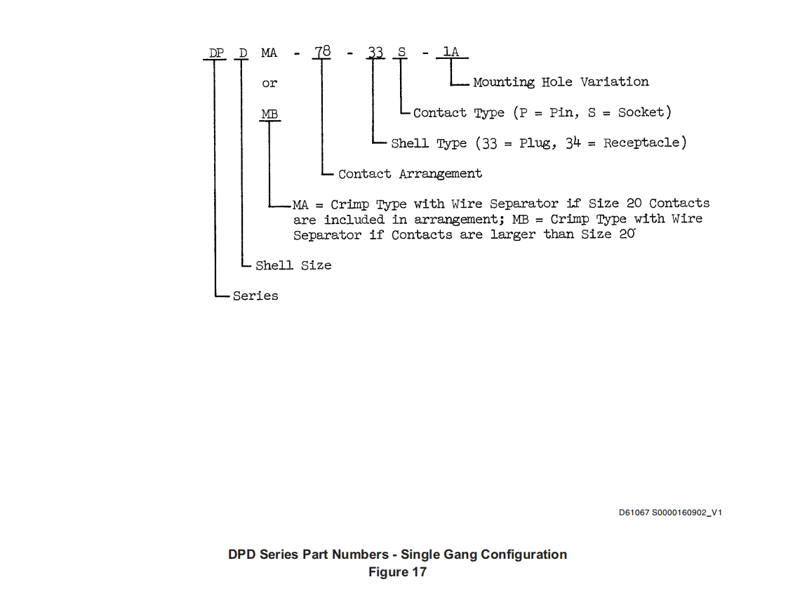
(2) Typical DPD Series Part Numbers
典型的 DPD 系列件号
(a) Single Gang Configuration (See Figure 17)
单组构型(见图 17)
(b) Two Gang Configuration (See Figure 18)
双组构型(见图 18)
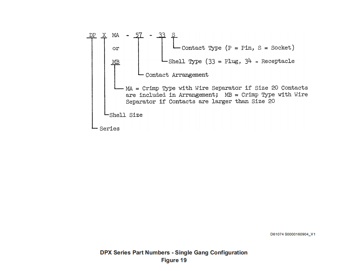
(3) Typical DPX Series Part Numbers
典型 DPX 系列件号
(a) Single Gang Configuration (See Figure 19)
单组构型(见图 19)
(b) Two Gang Configuration (See Figure 20)
双组构型(见图 20)
C. Removing Contacts from Connector
从连接器上拆下插针
(1) Select proper removal tool from Table 5.
从表 5 中选择合适的拆卸工具。
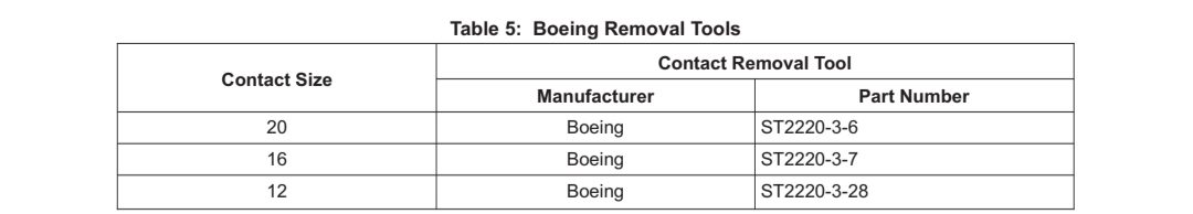
NOTE: Equivalent vendor tool may be used in place of above ST tools. One plastic removal tool is normally furnished for each contact size included with a new connector. Tool numbers are applicable for both pin and socket contacts.
注:可使用供应商提供的同等工具代替上述 ST 工具。通常情况下,新连接器的每种插针尺寸都配有一个塑料拆卸工具。工具编号适用于钉针和孔针插针。
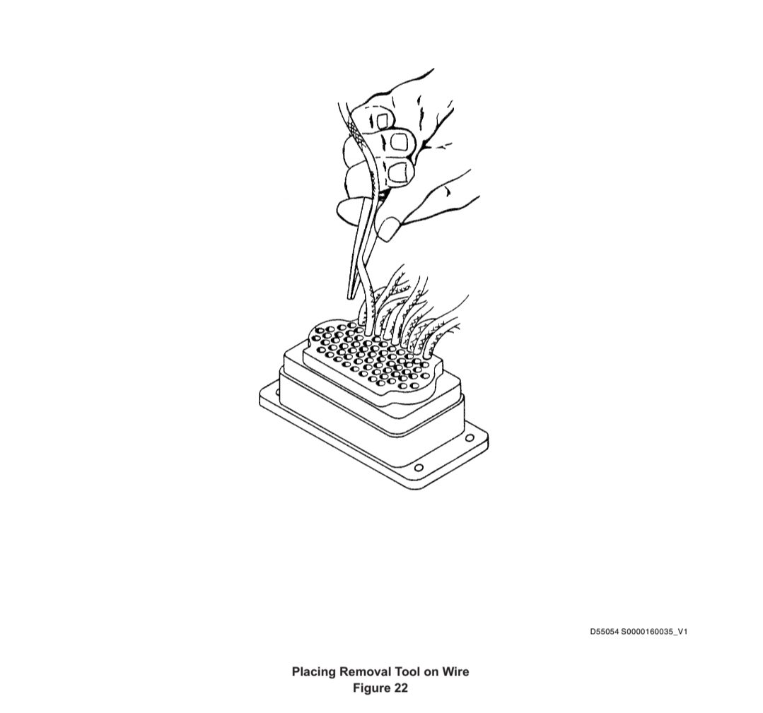
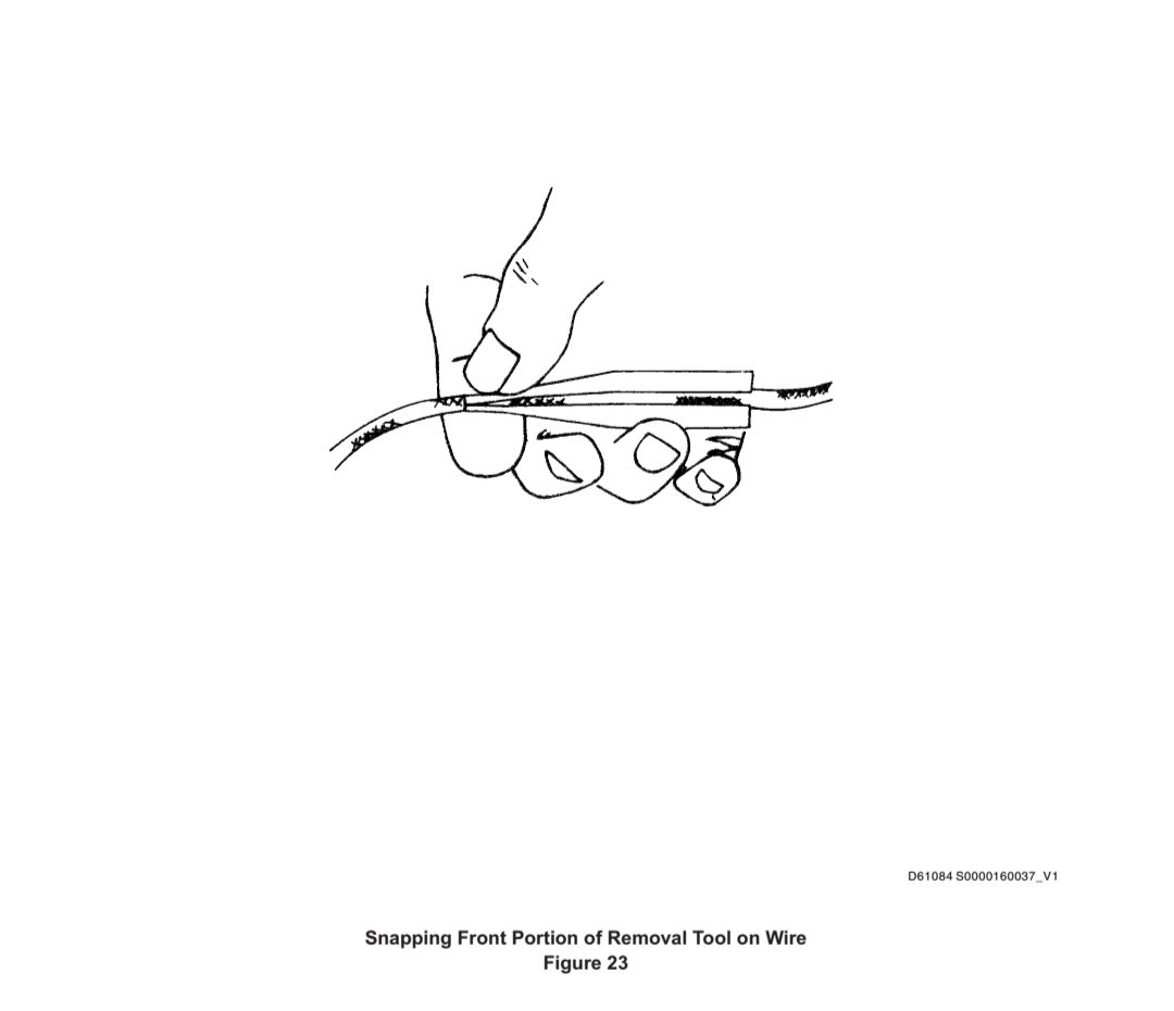
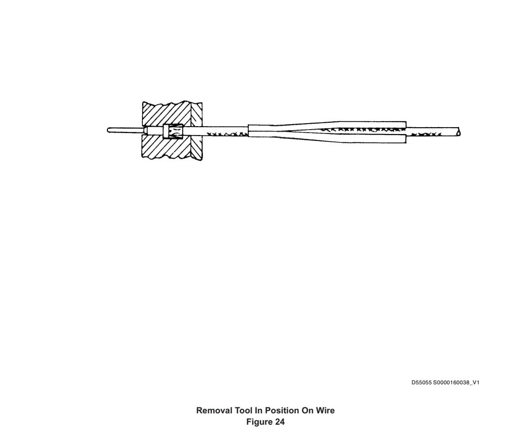
(2) Place removal tool on wire by sliding wire into back part of tool per Figure 22 and then snapping wire into front portion of tool per Figure 1 and Figure 24.
将拆卸工具放在导线上,按照图 22 将导线滑入工具的后部,然后按照图 1 和图 24 将导线卡入工具的前部。
NOTE: To facilitate contact removal, remove bundle ties to provide a length of free wire adjacent to rear surface of connector not less than two inches.
注:为便于拆卸插针,应拆除捆扎带,以便在连接器后表面附近留出不少于两英寸的空闲导线长度。
NOTE: When two wires terminate in a common contact, removal tool may be altered by removing a narrow section of plastic as shown in Figure 25.
注: 当两根导线端接在一个共同的插针上时,拆卸工具可通过去掉一个狭窄的塑料部分来改变,如图 25 所示。
(3) Slide tool along wire straight into insert cavity until tool bottoms (Figure 26 and Figure 27).
将工具沿导线笔直滑入插入腔,直至工具底部(图 26 和图 27)。
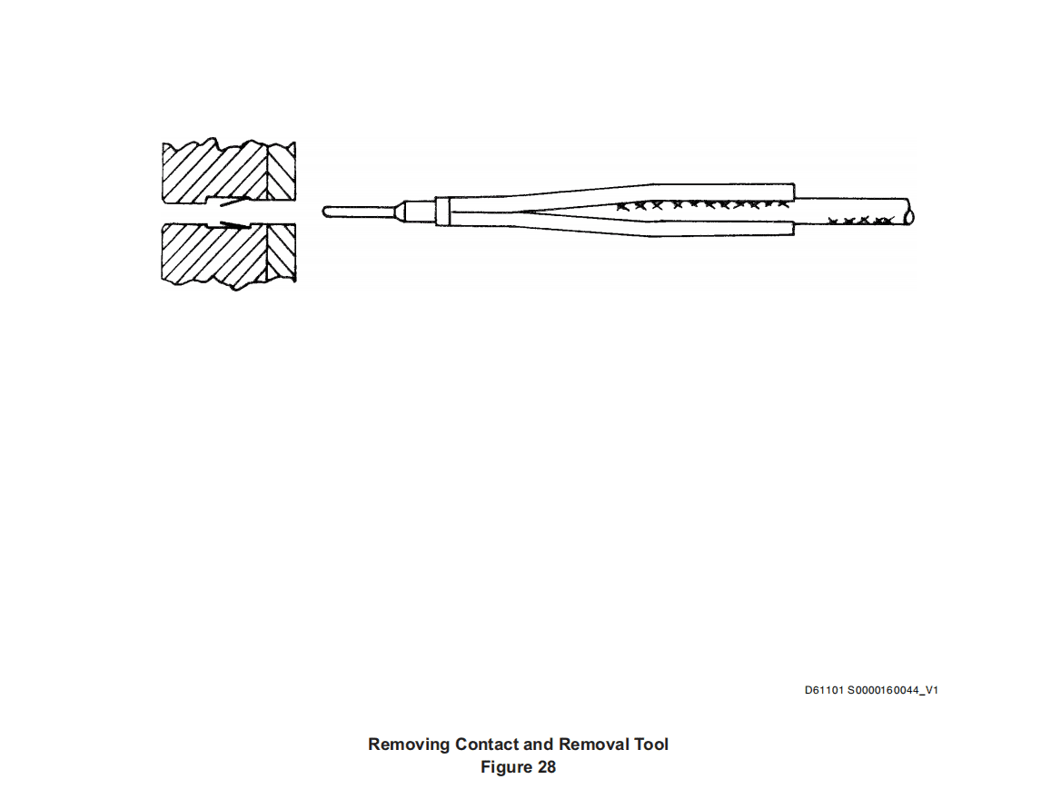
(4) Grasp wire and simultaneously remove contact and removal tool from insert cavity (Figure 28).
抓住导线,同时将插针和拆卸工具从插入腔中取出(图 28)。
D. Removing Wires from Solderless Contact
从无焊剂插针上拆卸导线
(1) Cut wire at end of contact barrel using wire cutters or similar tool.
使用剪线钳或类似工具在插针筒末端剪断导线。
E. Installing Contacts on Wire
在导线上安装插针
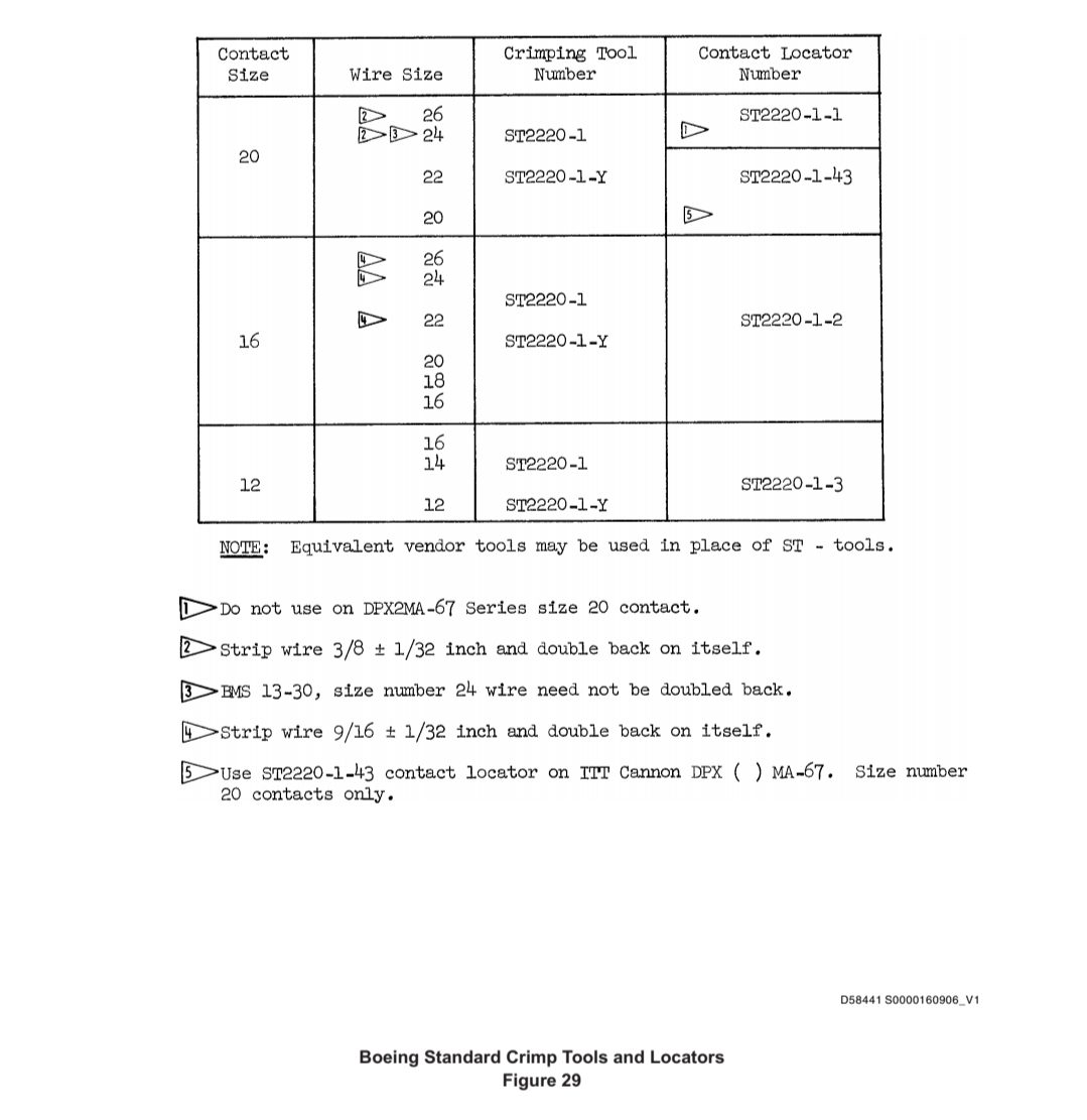
(1) Strip wire 3/16 ± 1/32 inch for size 20 contacts and 1/4 ± 1/32 inch for size 16 and 12 contacts.
对于 20 号插针,剥线 3/16 ± 1/32 英寸;对于 16 号和 12 号插针,剥线 1/4 ± 1/32 英寸。
(2) Crimp wires in contacts with tooling per Figure 29.
使用图 29 所示的工具将导线压接在插针上。
NOTE: Assemble DPA, DPD and DPX may contain coaxial contacts.
注:组装 DPA、DPD 和 DPX 时可能包含同轴插针。
F. Installing Contacts in Connector
将插针装入连接器
CAUTION:KEEP CONTACT ALIGNED PERPENDICULAR TO FACE OF CONNECTOR DURING INSERTION TO PREVENT DAMAGE TO WIRE SEPARATOR.
注意:在插入过程中,请保持插针与连接器表面垂直,以防止损坏分线器。
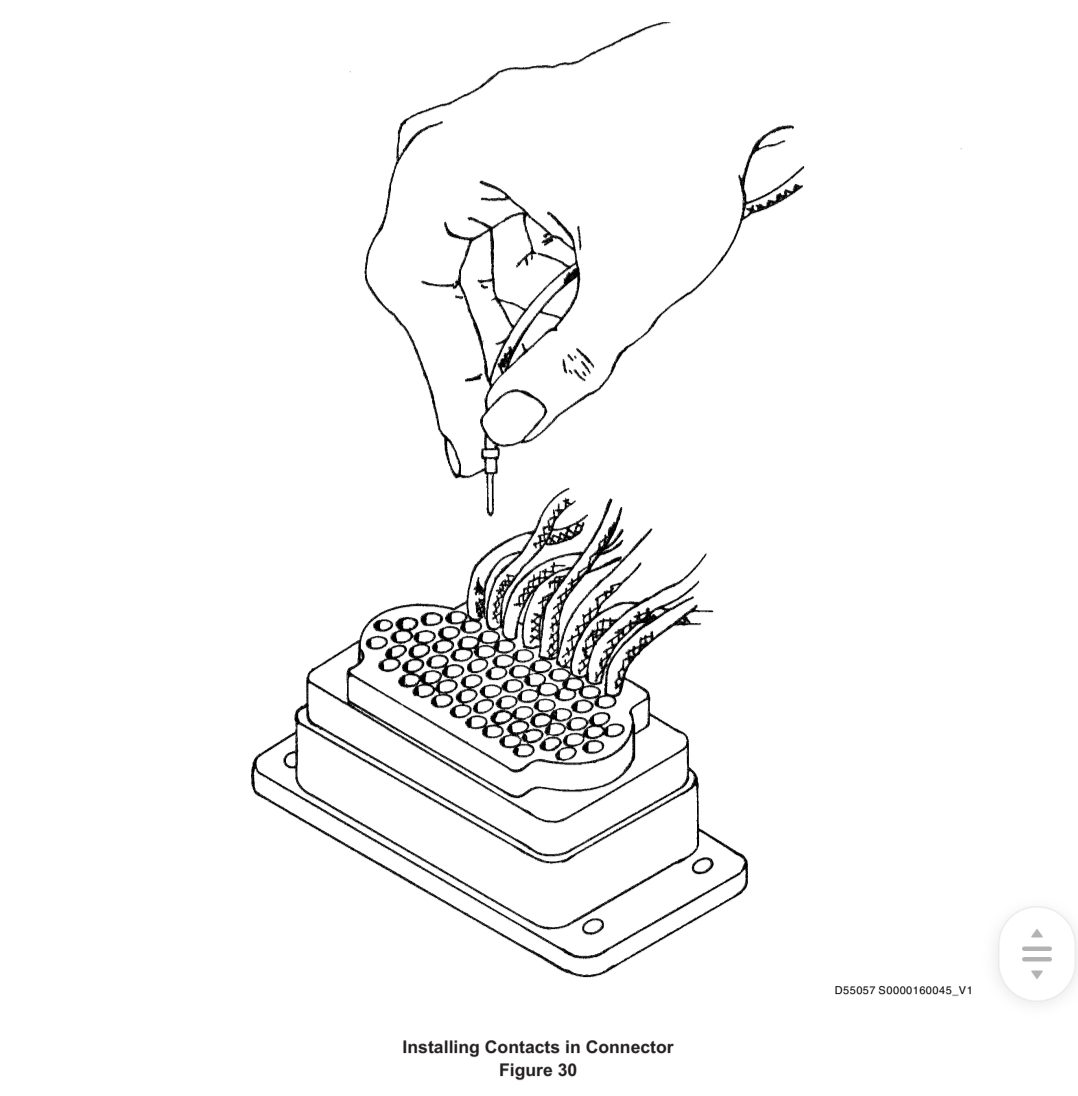
(1) Insert contact into contact cavity from rear of connector by gripping crimp portion of contact with finger tips and insert contact until contact shoulder has passed the resilient wire separator. After contact shoulder has passed wire separator, grip wire and carefully complete insertion until contact is locked in connector (Figure 30).
用指尖夹住插针的压接部分,将插针从连接器后部插入插针腔,直至插针肩部通过弹性导线分离器。插针肩部通过导线分离器后,握住导线,小心地完成插入,直至插针锁定在连接器中(图 30)。
NOTE: Contact insertion can usually be installed by hand without the use of a tool.
注: 插针插入通常可以用手完成,无需使用工具。
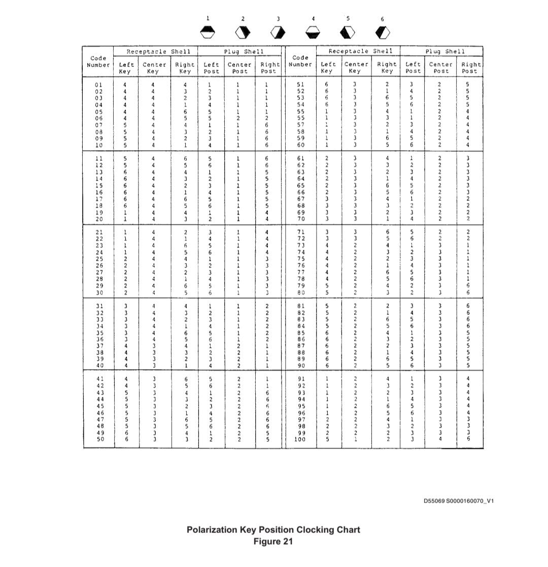
G. Polarization key position clocking chart, Figure 21 for two-gang DPX2 connectors. Dark, shaded position 1 thru 6 indicates the solid portion of a post or key. White, unshaded area indicates the open portion.
K键位置时钟图,图 21,适用于双组 DPX2 连接器。深色阴影位置 1 至 6 表示接线柱或K键的实心部分。白色无阴影区域表示开口部分。
CAUTION :DO NOT INDENT WIRE WITH FINGERNAIL(S).
注意 :不要用指甲压入导线。
(1) Check for proper seating of contact by grasping wire between thumb and forefinger only and pulling gently until thumb and forefinger slip on the wire.
仅用拇指和食指夹住导线,轻轻拉动直到拇指和食指在导线上滑动,检查插针是否正确就位。
NOTE: Contact insertion can be accomplished by hand and usually does not require any tools. If necessary, plastic removal tool can double as an insertion tool.
注: 插针插入可以用手完成,通常不需要任何工具。如有必要,可将塑料拆卸工具用作插入工具。


16. REPAIR OF AMP, INC. 5XXXXX- SERIES PRINTED CIRCUIT TYPE CONNECTORS 修理 AMP, Inc. 5xxxxx- 系列印制电路型连接器
A. Connector Description
连接器说明
(1) This connector is a one-piece, printed circuit board edge connector. The connector block contains preinserted contacts which mate in a firm wiping action with pads of printed board. Contact positions are numbered front and rear.
这种连接器是一体式印刷电路板边缘连接器。连接器块包含预装插针,这些插针与印刷电路板的盘牢固擦拭配合。插针位置前后均有编号。
(2) Tab terminals are inserted into rear of housing by hand. No insertion tooling is required.
用手将接片端子插入外壳后部。无需插入工具。
(3) This connector is primarily for two-sided boards and is available in two versions; the dual type contact and the quad type contact. The dual commons the two rear wire terminals to both sides of printed circuit board. The quad (with four rear-wire terminals) commons two rear wire terminals to the top of board and two to the bottom; the board in this case is not commoned.
这种连接器主要用于双面电路板,有两种类型:双插针和四插针。双插针将两个后接线端子连接到印刷电路板的两面。四接点(带四个后接线端子)的两个后接线端子与电路板顶部共用,两个与电路板底部共用;在这种情况下,电路板不共用。
(4) Tab terminals accommodate wire sizes 18 through 26.
接线片端子适用于 18 至 26 号导线。
B. Removing Contacts from Connector
从连接器上取下插针
(1) Use extraction tool 91011-1 for removing contacts used on dual-type connectors (two tab terminals per position).
使用拔出工具 91011-1,以拔出双型连接器上的插针(每个位置有两个插片端子)。
(2) Use extraction tool 91017-1 for removing contacts used on quad-type connectors (four tab terminals per position).
使用拔出工具 91017-1,拆卸四型连接器上的插针(每个位置四个插片端子)。
C. Removing Wires from Solderless Contact
从无焊剂插针上拆卸导线
(1) Cut wire at end of wire insulation, using wire cutters or similar tool.
使用剪线钳或类似工具在导线绝缘层末端剪断导线。
D. Installing Contacts on Wire
在导线上安装插针
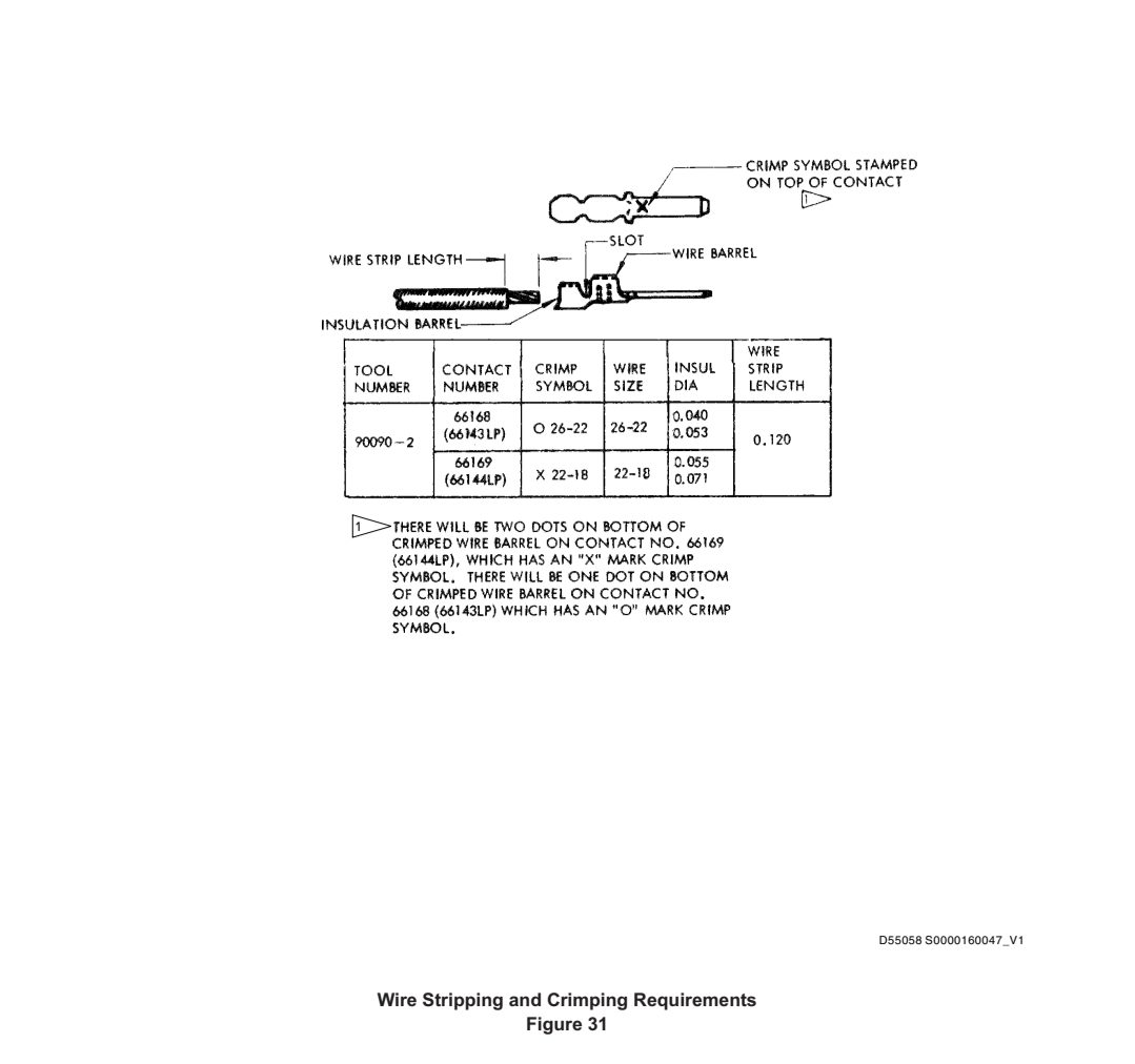
(1) Strip wire per Figure 31, using stripping tool ST2346 or equivalent.
使用 ST2346 或同等剥线工具,按图 31 剥线。
(2) Crimp wires in contacts with tooling per Figure 31.
按照图 31 使用工具将导线压接在插针上。
NOTE: Lubricate all pins, pivot points and bearing surfaces of tool as needed with S.A.E. No. 20 motor oil.
注: 根据需要用 S.A.E. 20 号机油润滑工具的所有销钉、支点和轴承表面。
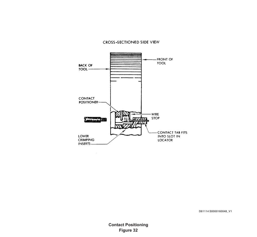
(a) Insert contact into back of tool 90090–2 so that contact tab fits into slot in locator (Figure 32). Make sure contact bottoms in locator.
将插针插入工具 90090-2 的背面,使插针插片插入定位器的插槽 (图 32)。确保插针位于定位器底部。
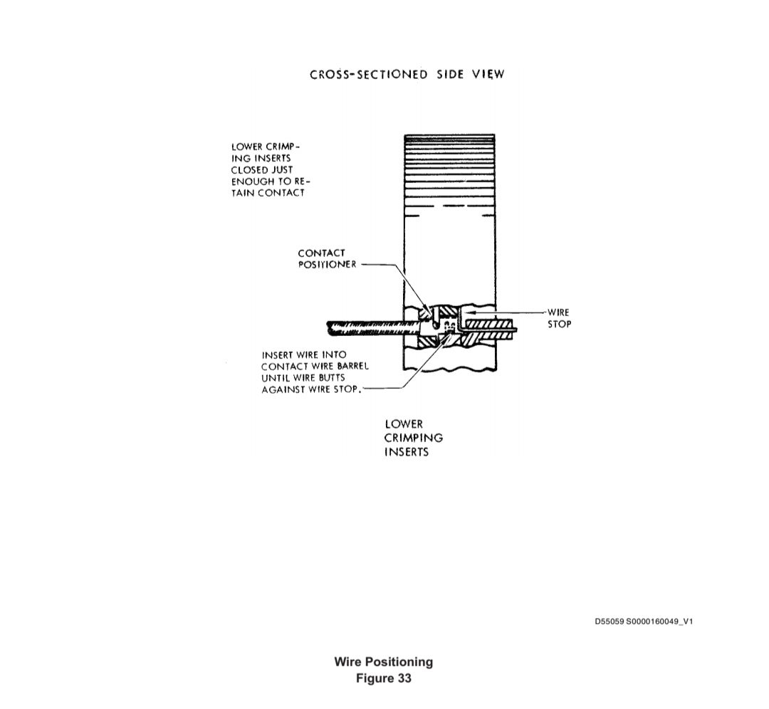
(b) Squeeze handles to raise lower crimping inserts just enough to retain contact (Figure 33). Do not deform contact wire or insulation barrels. As inserts close, contact positioner will engage contact.
挤压手柄,使下压接插片升高到足以保持插针 (图 33)。不要使接触线或绝缘筒变形。当插件闭合时,插针定位器将啮合插针。
(c) Insert stripped wire into contact wire barrel until wire butts against wire stop (Figure 33).
将剥皮的导线插入插针线筒,直到导线顶住导线挡块 (图 33)。
(d) Hold wire in place and finish crimp by closing handles until ratchet releases. Open tool handles and remove crimped contact from tool.
将导线固定到位,关闭手柄直到棘轮松开,完成压接。打开工具手柄,将压接好的插针从工具中取出。
E. Installing Contacts in Connector
将插针装入连接器
(1) Insert contact into rear of housing by hand.
用手将插针插入外壳后部。
(2) Check for proper seating of contact by grasping wire between thumb and forefinger only and pulling gently until thumb and forefinger slip on wire.
仅用拇指和食指夹住导线,轻轻拉动直到拇指和食指在导线上滑动,检查插针是否正确就位。
17. Repair of AMP, Inc. AM and AD Series Connectors 修理 AMP, Inc. AM 和 AD 系列连接器
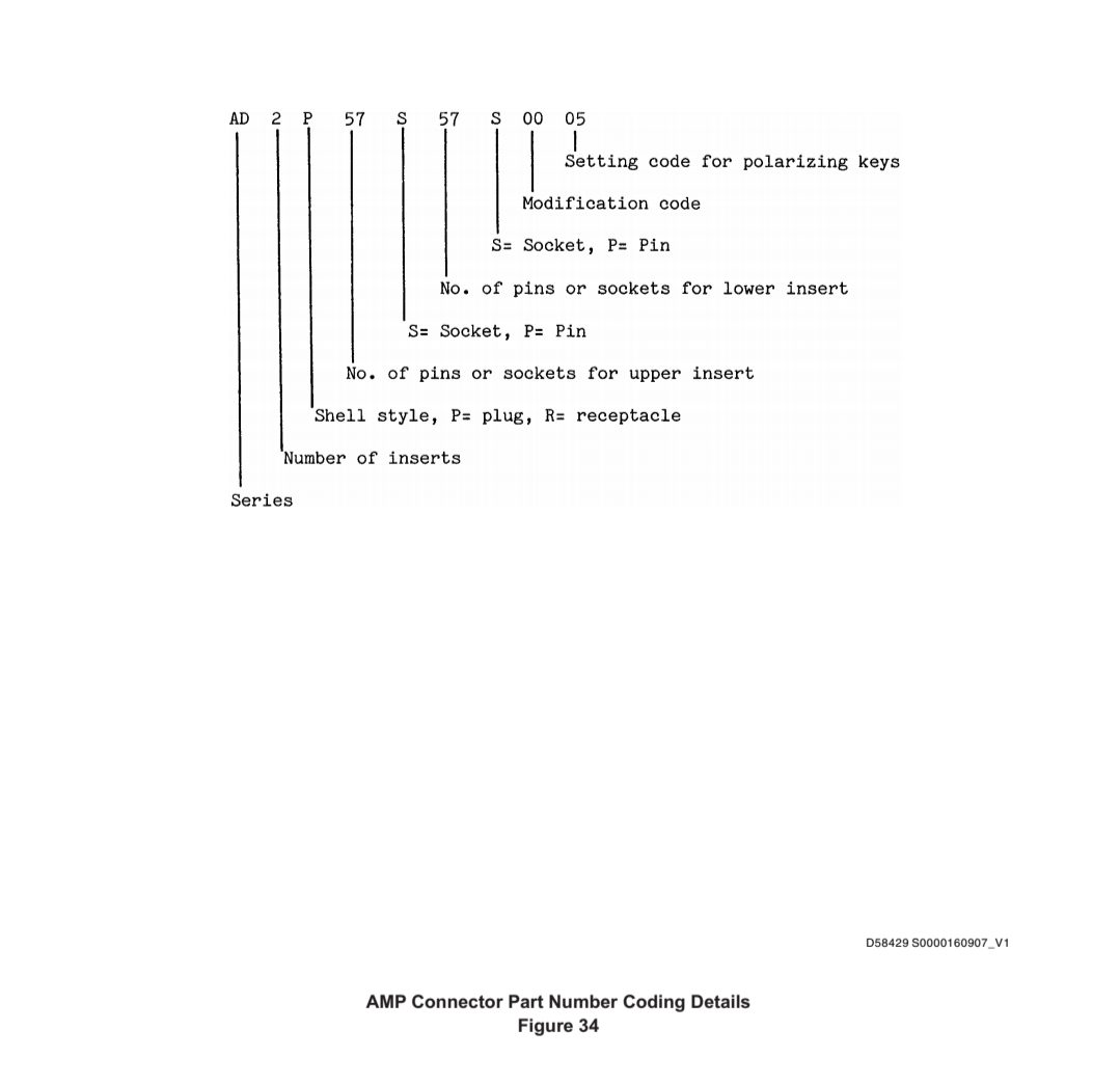
A. Part Numbering (See Figure 34)
件号(见图 34)
B. Typical contacts are listed in Table 6.
典型插针见表 6。

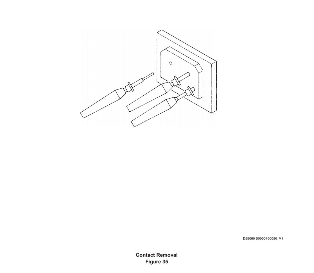
C. Contact Removal (Figure 35)
拆卸插针(图 35)
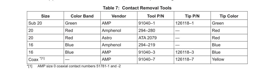
(1) Select removal tool from Table 7.
从表 7 中选择拆卸工具。
(2) Slide the removal tool tip into the insert and over the contact from the mating side. Insert carefully to avoid damage to grommet or retention clip.
将拆卸工具尖头滑入插入件,并从配合侧滑过插针。小心插入,以免损坏扣眼或固定夹。
(3) When removal tool is at bottom of grommet, advance plunger to eject contact.
当拆卸工具位于扣眼底部时,推进柱塞以顶出插针。
(4) Grasp freed contact with fingers (do not use pliers) and remove from insert.
用手指(不要使用钳子)抓住脱出的插针,然后从插件中取出。
(5) If sealing rod has been inserted in contact, do not remove rod before ejecting contact.
如果密封杆已插入插针,在顶出插针之前不要拔出密封杆。
(6) If contacts are difficult to remove, check tool tip for damage.
如果插针难以取出,检查工具头是否损坏。
D. Contact Insertion
插针插入
(1) Install contacts on wire
在导线上安装插针
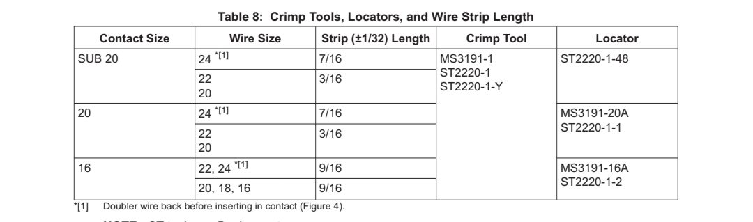
(a) Strip wire per Paragraph 8., PREPARATION OF WIRES. Strip length varies with contact and wire size per Table 8.
按照第 8.段“导线的准备”工作剥线。剥线长度因插针和导线尺寸而异,见表 8。
(b) Select locator and crimp tool from Table 8. Place contact in locator.
从表 8 中选择定位器和压接工具。将插针放入定位器。
(c) Insert stripped end of wire into crimp barrel until insulation is butted against barrel. Check that bared wire is visible in inspection hole (Figure 3).
将导线的剥皮端插入压接筒,直到绝缘层与压接筒对接。检查检查孔中是否能看到裸露的导线 (图 3)。
NOTE: Wire may be inserted in contact before placing contact in locator.
注:可在将插针放入定位器之前将导线插入插针。
(d) When wire is seated in contact, and contact shoulder seated in locator, close crimp tool handles until ratchet releases.
当导线插入插针,插针肩部插入定位器时,关闭压接工具手柄,直到棘轮松开。
(e) Remove contact/wire assembly from tool. Verify that no more than 1/32 inch of bared wire is exposed between insulation and contact barrel.
从工具中取出插针/导线组件。确认绝缘层和插针筒之间裸露的导线不超过 1/32 英寸。
NOTE: ST tools are Boeing parts.
注:ST 工具为 Boeing 零件。
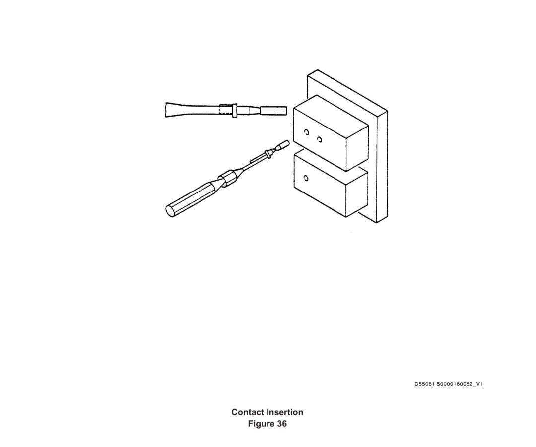
(2) Insert Contact Into Connector (Figure 36)
将插针插入连接器(图 36)
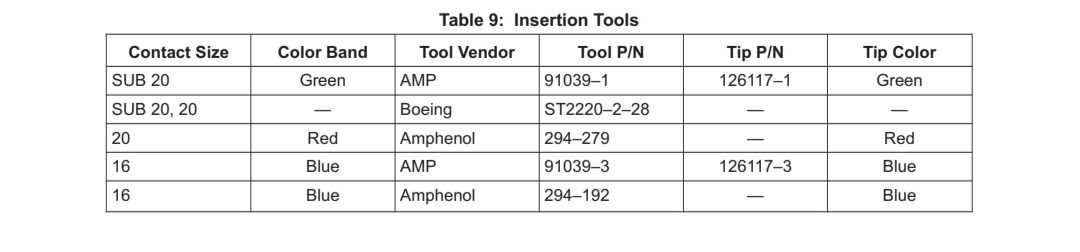
(a) Select insertion tool from Table 9.
从表 9 中选择插入工具。
(b) Slide contact into insertion tool tip as shown in Figure 36. Check that tool tip is not bent, spread, or flared, and that it is free of burrs or sharp edges that could damage connector. Tool tip should fit around crimp barrel (not rear edge).
如图 36 所示,将插针滑入插入工具尖端。检查工具尖是否弯曲、张开或外扩,是否有可能损坏连接器的毛刺或尖锐边缘。工具尖应与压接筒(而不是后缘)贴合。
(c) Withdraw tool carefully, retaining axial alignment until tool is clear of connector. Check by pulling on wire with thumb and forefinger (not fingernails) until wire slips between fingers.
小心抽出工具,保持轴向对准,直到工具离开连接器。用拇指和食指(不要用指甲)拉导线进行检查,直到导线在手指间滑动。
(d) Insert unwired contacts in all unused grommet holes with Boeing tool ST2220-2-23.
用波音工具 ST2220-2-23 将未接线的插针插入所有未使用的扣眼孔中。
(e) Insert sealing rods, smaller diameter end first, into all unwired contacts. Trim rods to leave 1/16 to 3/16 extension from insert face.
将密封杆,直径较小的一端先插入所有未接线的插针。修整密封杆,使其在插入面上留出 1/16 至 3/16 的延伸部分。
18. Repair of ITT Cannon FR, FV and Flight FC, FH Series Connectors (Ref BAC5162-53) 修理 ITT Cannon FR、FV 和 Flight FC、FH 系列连接器(参考编号 BAC5162-53)
A. Part Numbering
件号
(1) ITT Cannon Connectors (See Figure 37)
ITT Cannon 连接器(见图 37)
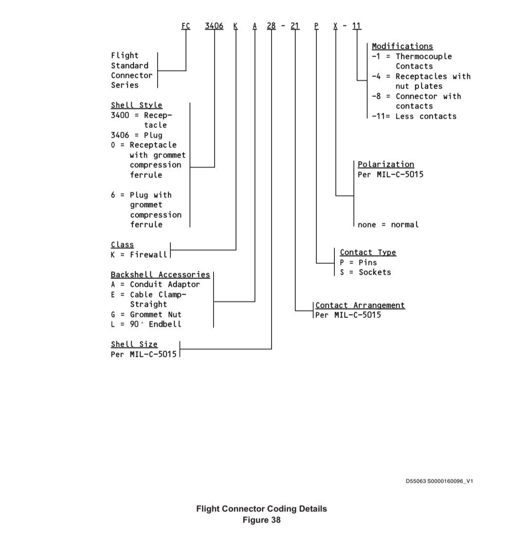
(2) Flight Connectors (See Figure 38)
飞行连接器(见图 38)
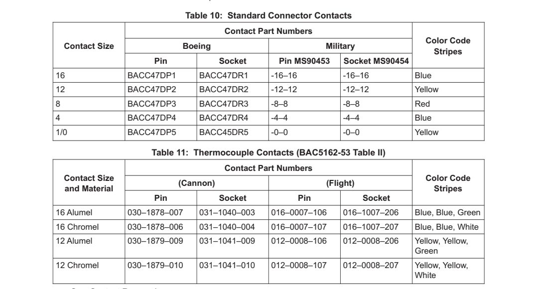
B. These connectors could have standard contacts or thermocouple contacts. Standard contacts are shown in Table 10. Thermocouple contacts are shown in Table 11.
这些连接器可能有标准插针或热电偶插针。标准插针如表 10 所示。热电偶插针如表 11 所示。
C. Contact Removal
拆卸插针
(1) Unscrew the cable clamp or end bell and slide the parts back over the wires.
拧松电缆夹或端环,将零件滑回到导线上。
(2) Use the removal tool per Table 12. Put the tool around the mating end of the contact, and down into the cavity until the tool tip touches the bottom. Move the plunger to partially eject the contact. Remove the tool carefully.
根据表 12 使用拆卸工具。将工具绕过插针的配合端,向下插入空腔,直到工具顶端触及底部。移动柱塞,将插针部分顶出。小心取出工具。
(3) Pull the wire and contact from the insert by hand. Do not use pliers to remove contacts.
用手将导线和插针从插件中拉出。不要使用钳子取出插针。


D. Contact Installation on Wire
在导线上安装插针
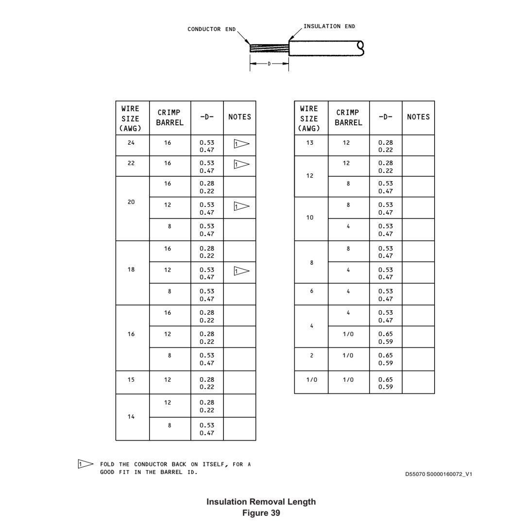
(1) Remove the insulation from the end of the wire to the stripped length D as shown in Figure 39.
如图 39 所示,将导线末端的绝缘层去除至剥离长度
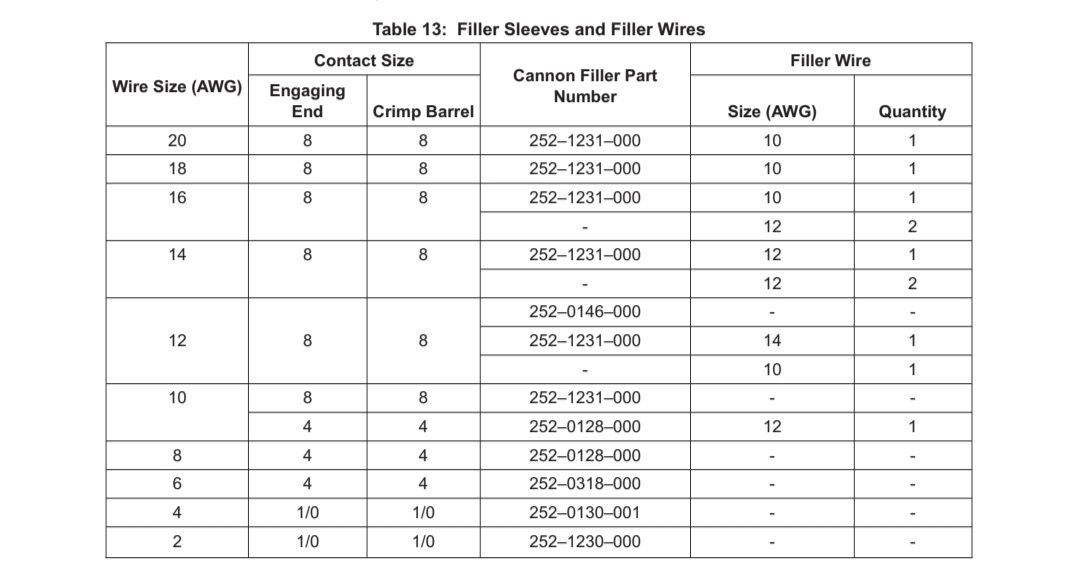
(2) When the wire size is smaller than that of the contact, use filler sleeves and filler wires per Table 13 to build up the undersized conductor.
当导线尺寸小于插针尺寸时,按照表 13 使用填充套管和填充导线来填充尺寸不足的导体。
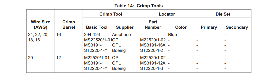
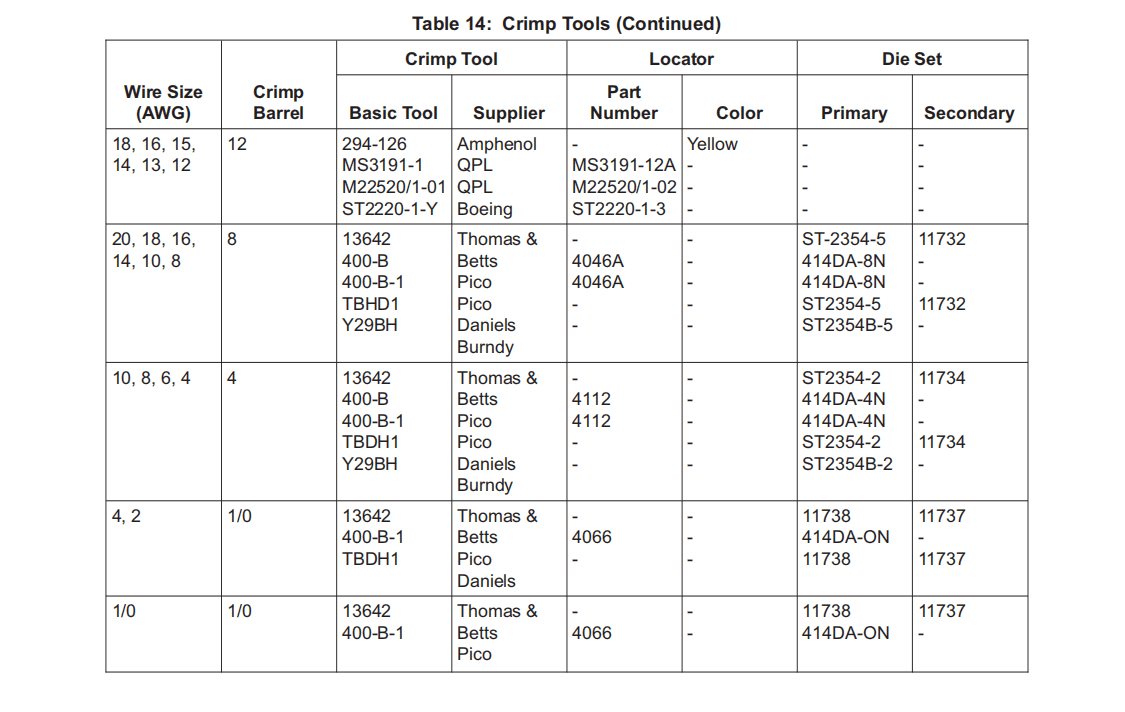
(3) Put the stripped end of the wire into the crimp barrel. Or put the contact in the locator or die set and then put the wire into the crimp barrel. Make sure all of the conductor strands are in the crimp barrel. Make sure you can see the conductor through the inspection hole. Put the contact and wire assembly in the crimp tool locator or die set per Table 14. For size 8 and larger contacts, put the contact in the dies with the open end of the contact barrel 0.01-0.03 inch inside the dies.
将导线的剥线端放入压线筒。或者将插针放入定位器或模具中,然后将导线放入压接筒。确保所有导体都在压接筒内。确保可以通过检查孔看到导体。按照表 14 将插针和导线组件放入压接工具定位器或模具中。对于 8 号和更大的插针,将插针放入模具中,使插针筒的开口端在模具内 0.01-0.03 英寸处。
(4) With the contact at the bottom of the locator or in the die set, close the crimp tool until the ratchet or the bypass valve releases.
将插针放在定位器底部或模具中,关闭压接工具,直到棘轮或旁通阀释放。
E. Contact Installation in Connector
在连接器中安装插针
(1) Slide the backshell hardware back up the wire bundle in the order for assembly. Do not try to remove or turn the resilient grommet or insert parts, because they are solid parts of the connector assembly.
按照装配顺序将后壳硬件滑回线束。不要试图拆卸或转动弹性扣眼或插入零件,因为它们是连接器组件的实心零件。
(2) Make sure the contacts are straight.
确保插针平直。
(3) If some of the contact locations of the connector will not be connected to wires, install spare contacts in these locations before you install the wired contacts.
如果连接器的某些插针位置不连接导线,请在这些位置安装备用插针,然后再安装接线插针。
(4) To install size 16 and size 12 contacts, hold the contact-wire assemblies one at a time and guide them into their related grommet cavities. Make sure the shoulder is flush to 0.09 inch from the grommet surface. Slide the specified insertion tool (Table 12) over the wire, and against the contact shoulder. Carefully push the insertion tool and contact until it stops. Pull out the tool carefully. Note that sizes 8, 4 and 1/0 contacts can be installed by hand without tools.
安装 16 号和 12 号插针时,每次握住一个插针-导线组件,将其导入相关的扣眼空腔。确保肩部距扣眼表面齐平至 0.09 英寸。将规定的插入工具(表 12)滑到导线上,并顶住接触肩。小心推动插入工具和插针,直至其停止。小心地拉出工具。请注意,8 号、4 号和 1/0 号插针可手工安装,无需工具。
(5) To make sure the contact is correctly installed, hold each wire between your thumb and forefinger only, and pull slowly until your thumb and forefinger slip on the wire. Do not jerk on the wire, or put a nick in the wire insulation with your fingernails.
为确保插针安装正确,仅用拇指和食指夹住每根导线,慢慢拉动,直到拇指和食指在导线上滑动。不要用力拉导线,也不要用指甲划伤导线绝缘层。
(6) Install grommet seal rods behind size 16 and 12 spare contacts.
在 16 号和 12 号备用插针后面安装扣眼密封杆。
F. Connector Parts Assembly
连接器零件组装
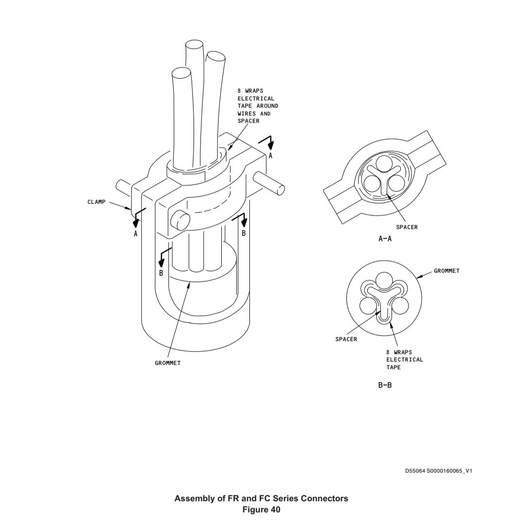
(1) When FRFXX28-22P, FRFXX28-22S , FC34XXKE28-22P and FC34XXKE28-22S series connectors or the optional FR series connectors are wired with AWG 4 wire, assemble the cable clamp as follows:
当 FRFXX28-22P、FRFXX28-22S、FC34XXKE28-22P 和 FC34XXKE28-22S 系列连接器或可选的 FR 系列连接器使用 AWG 4 导线接线时,请按以下步骤组装电缆夹:
(a) Wrap a BACS45A115 spacer with 8 wraps of Permacel Electrical P263 tape, and put it between the wires and next to the connector grommet (Figure 40).
用 8 卷 Permacel Electrical P263 胶带缠绕一个 BACS45A115 垫块,将其放在导线和临近连接器扣眼之间(图 40)。
(b) Put another BACS45A115 spacer between the wires and underneath the cable clamp. Wrap the wires in this area with 8 wraps of Permacel Electrical P263 tape. Put the tape wraps under the cable clamp.
将另一个 BACS45A115 垫块放在导线和电缆夹下方之间。用 8 卷 Permacel Electrical P263 胶带缠绕该区域的导线。将胶带包在电缆夹下面。
(2) When FRFXX36-5X or FC34XXKX36-5X connectors are wired with AWG 2 or 4 wire, complete connector assembly as follows:
当 FRFXX36-5X 或 FC34XXKX36-5X 连接器使用 AWG 2 或 4 导线接线时,按以下步骤完成连接器组装:
(a) When the endbell or cable clamp is supplied, assemble the endbell or cable clamp.
如果提供端环或电缆夹,则组装端环或电缆夹。
(b) Install a 1/2 inch diameter, 2 1/4 inch long, Teflon sealing rod in the unused cavity. Push the rod against the contact crimp barrel.
将直径 1/2 英寸、长 2 1/4 英寸的特氟龙密封杆安装在未使用的空腔中。将密封杆推到插针压接筒上。
(c) Slide Matrix spacer 6000-052-000 between the wires and sealing rod with the large end against the connector grommet.
将 Matrix 垫块 6000-052-000 放在导线和密封杆之间,大端顶住连接器扣眼。
(d) Complete the cable clamp assembly. If a cable clamp is not used, tie the wires and sealing rod over the grooved portion of the spacer with grade D lacing tape.
完成电缆夹组件。如果不使用电缆夹,则用 D 级绑带将导线和密封杆绑在垫块的凹槽部分上。
(3) Assemble the end bell or cable clamp and tighten it.
组装端环或电缆夹并拧紧。

19. Assembly of Kidde 876633 and 876635 Connectors 组装 Kidde 876633 和 876635 连接器
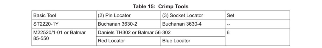
A. Assemble connector on 10-60816-17 wire (Preferred Method) — See Figure 41
将连接器组装到 10-60816-17 导线上 (首选方法) — 见图 41
(1) Discard spring (6).
丢弃弹簧 (6)。
(2) Strip woven jacket, tapes and silicon liner from wire for a distance of 1-1/12 inches. Do not nick or scrape asbestos wrap over conductor.
剥去导线上的编织护套、胶带和硅衬垫,距离 1-1/12 英寸。不要划伤或刮擦导体上的石棉包层。
(3) Strip asbestos wrap from conductor 11/32 inches
从导体上剥下 11/32 英寸的石棉包层
(4) Slide a 2-inch length of Penntube WTF #1241 sleeving (8) over wire.
将 2 英寸长的 Penntube WTF #1241 套管 (8) 套在导线上。
(5) Position both inner and outer layers of sleeving (8) even with end of asbestos wrap and shrink in place. Use heater-blower combination producing 750°F at point of application.
将套管 (8)的内层和外层与石棉包的末端对齐并收缩到位。使用可以使温度为750°F的加热吹风风机。
(6) Cut 3/4-inch lengths of Penntube WTF #1206, #1212, and #1204 sleeving and slide on wire in that order.
剪下 3/4 英寸长的 Penntube WTF #1206、#1212 和 #1204套管,并按顺序滑到导线上。
(7) Slide sleeve (5) and insulator (4) in that order over conductor and shrunk sleeving up to jacket cut-off (Figure 41).
依次将套管 (5)和绝缘体 (4)套在导线和收缩套管上,直至外套切口 (图 41)。
(8) Insert wire into contact (2, 876633 assembly) or (3, 876635 assembly) as far as possible.
将导线尽可能插入插针 (2,876633 组件)或 (3,876635 组件)。
(9) Crimp contact with one of the tools listed in Table 15.
使用表 15 中列出的工具之一压接插针。
(10) Mix Dow Corning RTV3112 with 5% catalyst S. (Pot life is 95 minutes at 60 to 80 degrees F.) Deaerate with a vacuum of at least 25 inches of mercury until foaming slows to a gentle boil. Release vacuum periodically to collapse excess foam.
将Dow Corning RTV3112 与 5% 的催化剂 S. 混合(在 60-80 ℉的条件下,贮放时间为 95 分钟),用至少 25 英寸汞柱的真空进行脱气,直至泡沫缓慢沸腾。定期释放真空,使多余的泡沫破裂。
(11) Apply compound around bare wire and where wire enters contact. Do not allow compound to extend across contact flange.
在裸露导线周围和导线进入插针的地方涂抹化合物。不要让化合物穿过插针法兰。
(12) Insert contact fully into connector body, holding sleeve (5) and insulator (4) away from connector body (1).
将插针完全插入连接器本体,使套管 (5) 和绝缘体 (4) 远离连接器本体 (1)。
(13) While holding contact in position, fill rear of connector body with RTV3112 compound with syringe. Fill slowly and avoid trapping air.
保持插针就位的同时,用注射器向连接器本体后部注入 RTV3112 化合物。慢慢注入,避免残留空气。
(14) Push insulator (4) into body and thread sleeve (5) into connector (left hand thread). Do not allow contact to slip back while assembling.
将绝缘体 (4) 推入主体,将套管 (5) 拧入连接器 (左旋螺纹)。装配时不要让插针向后滑动。
(15) Tighten finger-tight and wipe off excess compound. Cure 24 hours at room temperature.
用手指拧紧并擦去多余的化合物。室温下固化 24 小时。
(16) Push WTF #1204 sleeving against flair on connector sleeve (5) then shrink in place.
将 WTF #1204套管推到连接器套管(5)的喇叭口处,然后收缩到位。
(17) Push WTF #1212 sleeving over flair on sleeve (5) and against connector body (1) then shrink in place.
将 WTF #1212套管推过套管(5)上的喇叭口并抵住连接器本体(1),然后收缩到位。
(18) Push WTF #1206 over connector body (1) and against coupling nut retainer ring then shrink in place.
将 WTF #1206 套管推过连接器本体 (1) 并抵住耦合螺母固定环,然后收缩到位。
(19) Tie envelope containing sealing gaskets P/N 209592 to connector. One gasket is to be installed when coupling connector to sensing element. Follow instructions on envelope P/N 241833. Spare gaskets are to be tied to cable assembly with high temperature tying cord. If connector uncoupling is necessary, install new gasket.
将装有密封垫 P/N 209592 的封套绑在连接器上。将连接器与传感元件连接时,应安装一个密封垫。按照封套 P/N 241833 上的说明操作。备用密封垫要用高温绑线绑在电缆组件上。如果需要拆开连接器,请安装新垫圈。
B. Assemble connector on 10-60816-17 wire (Alternate Method) (Figure 41)
将连接器安装到 10-60816-17 电线上 (替代方法) (图 41)
NOTE: Connector end of spring may be modified to ease installation. Grip overlapped coil of spring with side-cutter plier and bend to remove overlap. Open last two coils (one spring wire thickness at most) to allow end of spring to be started over flare on connector sleeve. Do not enlarge coil diameter and do not modify both ends of spring.
注:可对弹簧的连接端进行修改,以方便安装。用侧切钳夹住重叠的弹簧线圈,弯曲以去除重叠部分。打开最后两个线圈(最多一个弹簧线粗细),使弹簧末端从连接器套筒的扩口处开始。不要扩大线圈直径,也不要修改弹簧的两端。
(1) Slide items in order over wire (7):
按顺序将各部件滑过导线 (7):
(a) Spring (6), overlapped end first
弹簧 (6),重叠端在先
(b) Sleeve (5)
套管 (5)
(c) Insulator (4)
绝缘体 (4)
(2) Strip wire 1/32 ±1/32 inch.
剥去导线 1/32 ±1/32 英寸。
(3) Insert wire into contact (2, 876633 assembly) or (3, 876635 assembly) as far as possible.
将导线尽可能插入插针 (2, 876633 组件) 或 (3, 876635 组件)。
(4) Crimp contact with one of the tools listed in Table 15.
使用表 15 中列出的一种工具压接插针。
(5) Mix Dow Corning RTV3112 with 5% catalyst S. (Pot life is 95 minutes at 60 to 80°F.) Deaerate with a vacuum of at least 25 inches of mercury until foaming slows to a gentle boil. Release vacuum periodically to collapse excess foam.
将Dow Corning RTV3112 与 5% 的催化剂 S. 混合 (在 60 至 80°F 温度下,贮放时间为 95 分钟)。定期释放真空,使多余的泡沫破裂。
(6) Apply compound around bare wire and where wire enters contact. Do not allow compound to extend across contact flange.
在裸露导线周围和导线进入接插针的地方涂抹化合物。不要让化合物穿过插针法兰。
(7) Insert contact fully into connector body, holding sleeve (5) and insulator (4) away from connector body (1).
将插针完全插入连接器本体,使套管 (5) 和绝缘体 (4) 远离连接器本体 (1)。
(8) While holding contact in position, fill rear of connector body with RTV3112 compound with syringe. Fill slowly and avoid trapping air.
保持插针就位,用注射器向连接器本体后部注入 RTV3112 化合物。慢慢注入,避免残留空气。
(9) Push insulator (4) into body and thread sleeve (5) into connector (left hand thread). Do not allow contact to slip back while assembling.
将绝缘体 (4) 推入主体,并将套管 (5) 拧入连接器 (左旋螺纹)。装配时不要让插针向后滑动。
(10) Tighten finger-tight and wipe off excess compound. Cure 24 hours at room temperature.
用手指拧紧并擦去多余的化合物。室温下固化 24 小时。
(11) Crimp sleeve (5) in area between threads and flare using Buchanan tool 612648 with die 614499.
使用Buchanan工具 612648 和模具 614499,在螺纹和扩口之间的区域压紧套管 (5)。
(12) Slide spring (6) forward and screw over flared portion of sleeve (left hand thread). A fair amount of force must be used to start the first coil over flare.
向前滑动弹簧 (6),拧在套管的扩口部分 (左旋螺纹)上。必须使用相当大的力来启动喇叭口上的第一个线圈。
(13) Tie envelope containing sealing gaskets P/N 209592 to connector. Gasket is to be installed when coupling connector to sensing element, with new gasket installed each time connector is uncoupled. Detailed instructions are on P/N 241833 envelope. The spare gaskets are to be tied to cable assembly with high temperature tying cord.
将装有密封垫 P/N 209592 的封套绑在连接器上。在将连接器连接到传感元件时应安装密封垫,每次松开连接器时都应安装新的密封垫。P/N 241833 封套上有详细说明。备用密封垫要用高温绑绳绑在电缆组件上。
20. Assembly of Sperry 1510731-902 connector 装配 Sperry 1510731-902 连接器
A. Materials and Equipment
材料和设备
NOTE: Equivalent substitutes can be used.
注: 可使用同等替代品。
(1) Sleeve, outer — BACS13S287C
(2) Sleeve, inner — BACS13S225B
(3) Cable — BMS 13-31 or BMS 13-58, Type 3, Class 2, 18-gage conductors (replaces BMS 13-18, Type 3, Class 2)
(4) Flux, acid — Amco 121, V70540
(5) Solder, 95% tin, 5% antimony — QQ-S-571, alloy SB5WS
(6) Flux — Kester 1544, V14597
(7) Solvent — MEK, aliphatic naphtha or isopropyl alcohol (Ref SOPM 20-60-01)
(8) Lacquer thinner
(9) Lockwire, CRES, 0.020 inch dia. — MS20995C20 (Ref SOPM 20-60-04)
B. Equipment
设备
NOTE: Equivalent substitutes can be used.
注: 可使用同等替代品。
(1) Swaging tools — Thomas and Betts WT211-14 tool, 214 die, V56501
(2) Stripper, wire — ST2222-38
(3) Resistance soldering tool
(4) Brush, soft bristle
(5) Megohmmeter, 500-volt
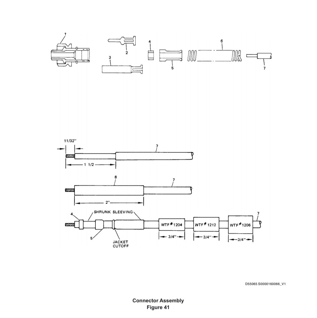
C. Connector installation (Figure 42)
安装连接器(图 42)
(1) Remove the outer jacket from the end of the cable to the length shown.
从电缆末端取下外层护套,长度如图所示。
(2) Slide the outer sleeve over the cable. Push it down the cable, away from the end.
将外护套套在电缆上。将其推下电缆,远离末端。
(3) Cut off the shield braid to the length shown.
切断屏蔽编织层,长度如图所示。
(4) Open up the outer end of the shield braid and slide the inner sleeve under the shield braid until the inner end of the sleeve is at the outer end of the cable jacket.
打开屏蔽编织层的外端,将内套管滑入屏蔽编织层下方,直至套管内端位于电缆护套的外端。
(5) Slide the outer sleeve to the end of the cable until the inner end is at the end of the cable jacket.
将外套管滑向电缆末端,直至内端位于电缆护套末端。
(6) Swage the sleeves with the swaging tool.
使用压接工具压接套管。
(7) If there are strands of shield braid that extend out from the end of the sleeves, cut them off.
如果屏蔽编织线从套管末端伸出,则将其剪断。
(8) Cut the internal conductors and remove the insulation from the ends to the dimensions shown. Be careful not to cut or nick the wires with the wire stripper.
按照图示尺寸剪断内部导体并去除两端的绝缘层。小心不要用剥线钳割断或割伤导线。
(9) Make sure the eyelets of the connector are straight. Do not use a connector with eyelets that are not straight.
确保连接器的孔眼是直的。不要使用孔眼不直的连接器。
CAUTION:THE GLASS HEADER IN THE CONNECTOR IS EASILY DAMAGED. BE VERY CAREFUL NOT TO BREAK IT OR BEND THE EYELETS.
注意:连接器中的玻璃头很容易损坏。小心不要弄破或弄弯孔眼。
(10) Apply acid flux to the eyelets of the connector. Do not let the flux get on the pin below the eyelet or on the glass seal.
在连接器的孔眼上涂抹酸性助焊剂。不要让助焊剂沾到孔眼下面的引脚或玻璃密封圈上。
(11) With the soldering tool, apply solder to the eyelet. Do not let the eyelet get too hot. Be sure to remove the heat if the eyelet starts to glow red.
用焊接工具将焊料涂到孔眼上。不要让孔眼太热。如果孔眼开始发红,请务必移除热量。
(12) Let the connector cool. Then put the header under hot running water and remove the acid flux residue with the brush. Be sure to clean the area around the glass seal.
让连接器冷却。然后将接头放在热水中,用刷子清除酸性助焊剂残留物。请务必清洁玻璃密封圈周围的区域。
(13) Solder the wires to the eyelets as shown. Use the Kester flux with the solder. Apply the flux only to the wire and to the eyelet part of the connector pin. Move the wire back and forth in the eyelet as necessary to make the solder flow in to make a good bond between the wire and the eyelet. But be careful not burn the flux or make the eyelet too hot.
如图所示,将导线焊接到孔眼上。在焊接时使用 Kester 助焊剂。仅将助焊剂涂抹在导线和连接器插针的孔眼零件上。根据需要在孔眼中来回移动导线,使焊料流入,使导线和孔眼之间结合良好。但要注意不要烧坏焊剂或使孔眼温度过高。
(14) Let the connector cool. Then put the connector header in solvent for 10-15 minutes. Every few minutes, use a brush to clean all parts of the connector. Be sure to include the glass seal.
让连接器冷却。然后将连接器头放入溶剂中 10-15 分钟。每隔几分钟,用刷子清洁连接器的所有零件。确保包括玻璃密封圈。
(15) Examine the solder joints. Make sure that:
检查焊点。确保:
(a) The solder joints are clean, continuous, shiny and have no pores or unwanted matter.
焊点干净、连续、有光泽,没有气孔或多余物质。
(b) The conductor insulation has no signs of heat damage. Some discoloration is acceptable.
导体绝缘没有热损坏的迹象。有些变色是可以接受的。
(c) The solder connections have no flux residue or splashed solder.
焊点没有助焊剂残留或焊料飞溅。
(d) The wire is not damaged at the end of the insulation.
导线绝缘末端无损坏。
(16) Remove dye from the corners of the outer sleeve with lacquer thinner.
用稀释剂清除外套管四角的染料。
(17) Install the clamp on the cover with short screws. Be sure to pull the shield braid tight before you tighten the screws.
用短螺钉将夹子安装到盖子上。在拧紧螺丝之前,务必拉紧屏蔽编织带。
(18) Lockwire the screws per SOPM 20-50-02.
按照 SOPM 20-50-02 将螺丝打保险。
D. Make sure the resistance between the conductors, and between each conductor and the connector shell, is a minimum of 5 megohms at 500 volts.
确保导体之间以及每个导体与连接器外壳之间在 500 伏特电压下的绝缘电阻至少为 5 兆欧。
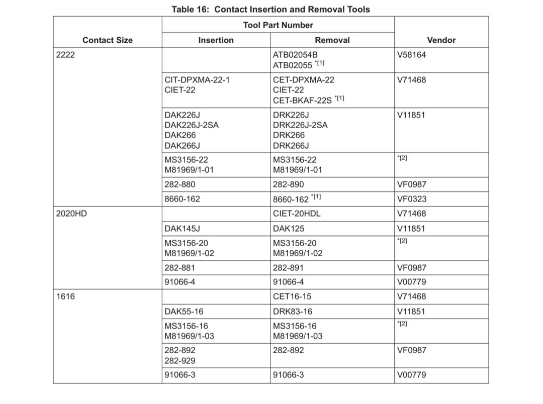
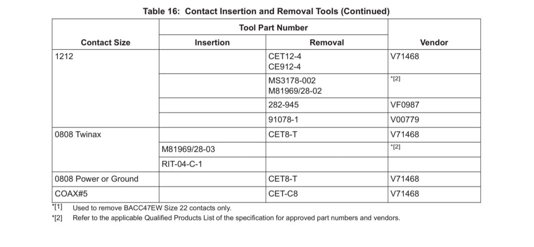
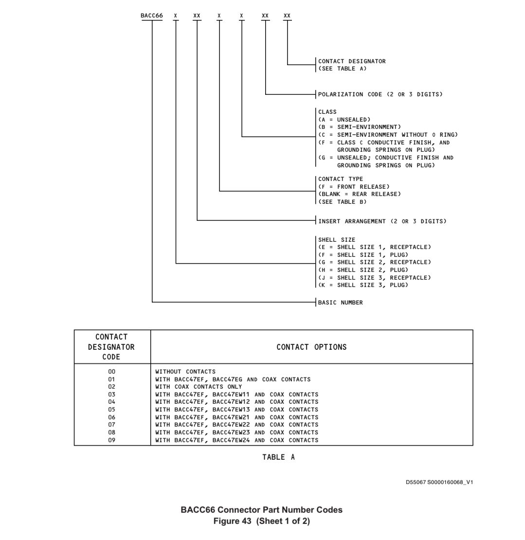
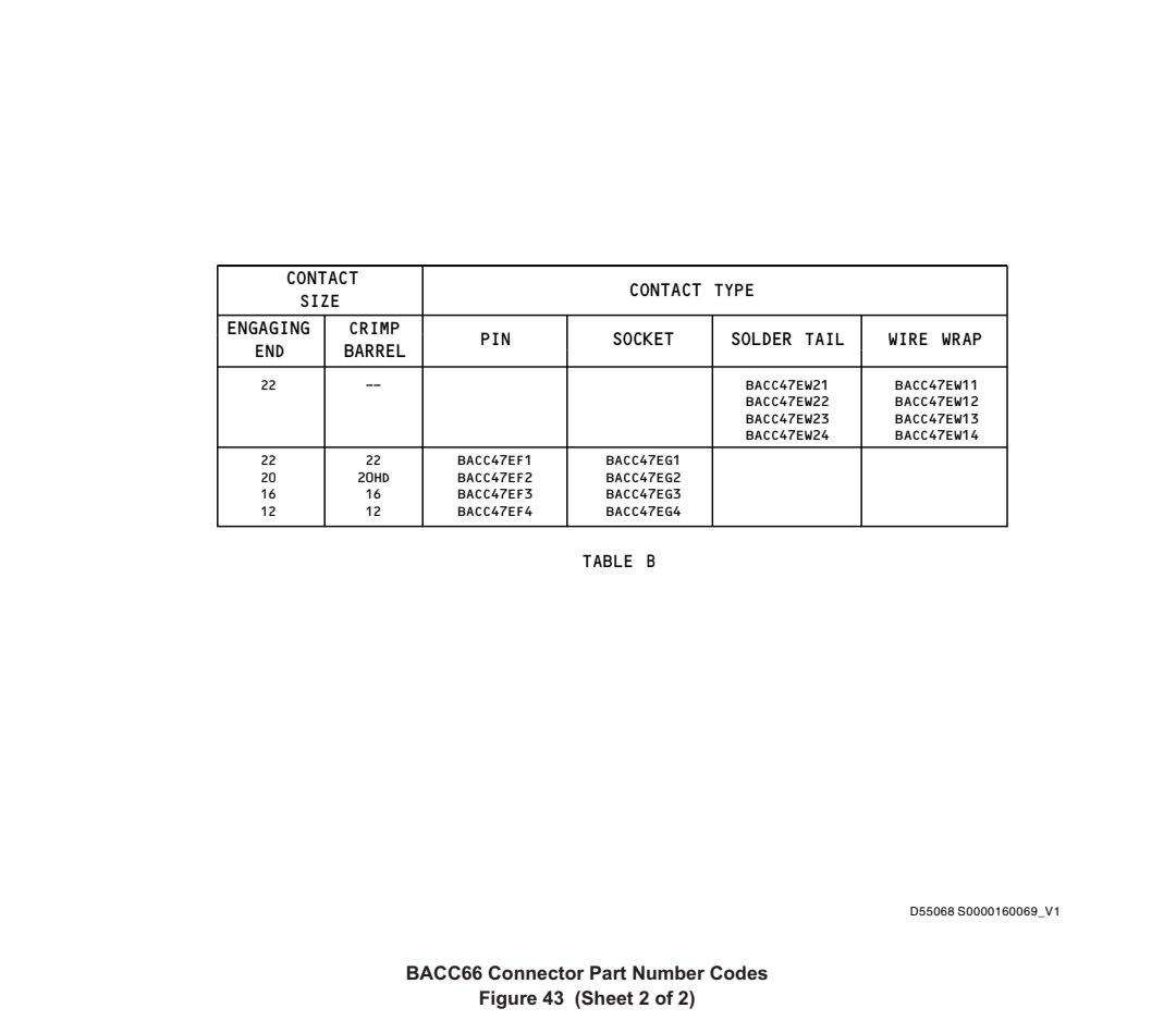
21. Repair of BACC66E thru BACC66K Series Connectors 修理 BACC66E 至 BACC66K 系列连接器
A. Part Number Codes — See Figure 43
件号代码 — 见图 43
B. Contact Removal
插针拆卸
(1) Use the applicable removal tool from Table 16.
使用表 16 中适用的拆卸工具。
(2) To remove crimp-type contacts:
拆除压接式插针:
(a) Slide the removal tool along the wire and into the insert cavity until the tool is at the bottom.
将拆卸工具沿导线滑入插入腔,直至工具位于底部。
(b) Hold the wire and the removal tool at the same time and remove them from the insert cavity.
同时握住导线和拆卸工具,将其从插件腔中取出。
1) If the removal tool has an indicating ring, slide the tool along the wire and into the insert cavity until the indicating ring is flush with the top of the surface of the rubber grommet.
如果拆卸工具带有指示环,则将工具沿导线滑入插件腔,直到指示环与橡胶扣眼表面的顶部齐平。
2) If the contact does not release, remove the tool, turn it 90 degrees and try again.
如果插针没有松开,请取下工具,旋转 90 度后再试一次。
(3) To remove BACC47EW front release contacts:
拆卸 BACC47EW 前退式插针:
CAUTION :MAKE SURE YOU REMOVE ALL WIRE PARTICLES AND UNWANTED SOLDER BEFORE YOU REMOVE A CONTACT. A THIN LAYER OF SOLDER CAN STAY ON SOLDER-TAIL CONTACTS.
注意 :在拆卸插针之前,请确保清除了所有电线颗粒和多余的焊料。焊尾插针上可能会有一层薄薄的焊锡。
(a) To remove the wire from a wire-wrap contact, unwrap it per SOPM 20-11-06. To remove the wire from a solder tail contact, desolder it per SOPM 20-12-01.
要从绕线插针上拆除导线,请按照 SOPM 20-11-06 将其拆开。要从焊尾插针上拆下导线,请按照 SOPM 20-12-01 进行拆焊。
(b) Carefully put the removal tool into the contact cavity from the front of the insert. Remove the contact and the removal tool at the same time from the connector. To help removal, apply light pressure on the contact from the rear.
小心地将拆卸工具从插件的前端放入插针空腔。同时从连接器上拆下插针和拆卸工具。为帮助拆卸,请从后面轻压插针。
C. Install Wire on Contact
在插针上安装导线
(1) If this is a contact with a crimp barrel, strip the wire, install it in the crimp barrel and crimp it per BAC5162-59.
如果这是一个带压接筒的插针,则剥去导线,将其安装到压接筒中,并按照 BAC5162-59 进行压接。
(2) If this is a contact with a wire wrap post or solder tail, do not install the wire on the contact at this time. The wire will be installed on the contact after the contact is installed in the connector.
如果是带绕线柱或焊尾的插针,此时不要将导线安装到插针上。导线将在插针安装到连接器后安装到插针上。
D. Install Contact Into Connector.
将插针安装到连接器中。
(1) Use the applicable insertion tool from Table 16.
使用表 16 中适用的插入工具。
(2) Put the contact in the insertion tool.
将插针放入插入工具。
CAUTION :KEEP THE CONTACT AND THE INSERTION TOOL ALIGNED PERPENDICULAR TO THE FACE OF THE CONNECTOR DURING INSTALLATION TO PREVENT DAMAGE TO THE WIRE SEPARATOR.
注意 :在安装过程中,请保持插针和插入工具垂直于连接器的表面,以防损坏分线器。
(3) For BACC47EF and EG crimp style contacts, align the contact and the insertion tool perpendicular (approximately 90 degrees) to the back of the insert. For BACC47EW front release contacts, align the contact and insertion tool perpendicular (approximately 90 degrees) to the front of the insert.
对于 BACC47EF 和 EG 压接式插针,将插针和插入工具垂直(约 90 度)对准插件背面。对于 BACC47EW 前退式插针,将插针和插入工具垂直于插件前端(约 90 度)。
(4) Guide the contact into the contact cavity. Put it in from the rear if this is a rear release contact or from the front if this is a front release contact If this is a wire wrap contact, make sure the flats on the wire-wrap post are aligned with the flats in the contact cavity.
将插针导入插针腔。如果是后退式插针,则从后面插入;如果是前退式插针,则从前面插入。如果是绕线插针,确保绕线柱上的平面与插针腔内的平面对齐。
(5) Push on the contact until you hear or feel a click as it locks into the connector.
推动插针,直到听到或感觉到插针锁入连接器的咔嗒声。
CAUTION :DO NOT PUT A NICK IN THE WIRE WITH YOUR FINGERNAIL.
注意 :不要用指甲在导线上划出缺口。
(6) To make sure the contact is completely installed, hold the wire between your thumb and forefinger only and pull lightly until they slip on the wire.
为确保插针完全安装,请用拇指和食指夹住导线,轻轻拉动,直到拇指和食指在导线上滑动。
E. Install wires on BACC47EW-series contacts.
在 BACC47EW 系列插针上安装导线。
(1) Strip the wires and install them on the wire-wrap posts per SOPM 20-11-06.
按照 SOPM 20-11-06 将导线剥开并安装在绕线柱上。
(2) Strip the wires and install them on the solder tails per SOPM 20-12-01.
按照 SOPM 20-12-01 将导线剥皮并安装到焊尾上。