仪表盘电气模块通用信息INSTRUMENT PANEL ELECTRICAL MODULE GENERAL INFORMATION
1. INTRODUCTION 介绍
A. The airplane instrument panel contains electrical modules which have a baseplate assembly, indicating lights, control switches, power connectors (light bases), and a wire bundle assembly. Some modules also include printed circuit card assemblies. The baseplate assembly has quick release fasteners which let you remove the module as a unit from the instrument panel. The baseplate and clamps can hold many different types of indicating instruments.
飞机仪表板包含电气模块,其中有底板组件、指示灯、控制开关、电源连接器(灯座)和电线束组件。某些模块还包括印刷电路板组件。底板组件带有快速释放紧固件,可将模块作为一个整体从仪表板上拆下。底板和夹具可容纳多种不同类型的指示仪表。
B. Refer to the Electrical and Electronics Wiring Diagram Manual for the schematic diagrams which show how the modules are connected in a system or part of a system.
请参阅《电气和电子接线图手册》,了解显示模块在系统中或系统一部分中如何连接的原理图。
C. The subject includes some procedures for annunciators S231T290-series and S231T300 series. These are Boeing Specification part numbers, and are related to the vendor part numbers in Table 1. For more details, refer to the Boeing Specification Cross Reference Index D6-42448.
该主题包括 S231T290 系列和 S231T300 系列信号器的一些程序。这些是波音规范的件号,与表 1 中的供应商件号有关。有关详细信息,请参阅波音规范对照索引 D6-42448。

D. Some of the units could have overhaul instructions in manuals written by the vendor or manufacturer. Refer to the Boeing Overhaul Manual/Component Maintenance Manual Index D6-47081 for a list of part numbers and available manuals. If the vendor’s overhaul instructions are different from the instructions in this subject, use the vendor’s overhaul instructions.
一些设备可能在供应商或制造商编写的手册中包含大修说明。有关件号和可用手册的列表,请参阅波音大修手册/部件维护手册索引 D6-47081。如果供应商的大修说明与本主题中的说明不同,请使用供应商的大修说明。
E. This subject also includes procedures for some vendor-made lightplates. These lightplates have different specification part numbers and vendors, but the procedure for all of them is the same. Instructions could be printed on some lightplates to tell you to use this procedure. Refer to Paragraph 7., for details.
本主题还包括一些供应商制造的灯盘的程序。这些灯盘有不同的规格件号和供应商,但所有灯盘的程序是相同的。一些灯盘上可能印有说明,告诉您使用此程序。详情请参阅第 7 段。
F. Refer to SOPM 20-00-00 for a list of all the vendor names and addresses.
有关所有供应商的名称和地址,请参阅 SOPM 20-00-00。
2. MATERIALS 材料
A. Aliphatic naphtha (Ref SOPM 20-60-01)
B. Captive screws, lightplate — S0050001-1 (V9U239)
C. Isopropyl alcohol (Ref SOPM 20-60-01)
D. Lacing Tape — BMS 13-54 or MIL-T-43435
E. Light bulbs, lightplate — No. 50001, 6832T1 short, 5-volt, 0.06 amp, unbased (V9U239 or V58774)
F. Loctite Adhesive — Superbonder Adhesive No. 416 (V05972)
G. Loctite Compound — Nutlock Compound 83 (Replaces Compound 74) (V05972)
H. Loctite primer — Grade T (V05972)
I. Paint, lightplate — See Table 5
J. Power connector, lightplate — S0050002 (V9U239) or 800000119 (V05617)
K. RTV Primer — Dow Corning 1204 (V71984)
L. Sealant — Dow Corning 3145RTV (V71984)
M. Sleeving — Varglas non-fray, Type HD or HP (V79074)
N. Wire ties, colored — Panduit SST1.51-series, SST21-series, SST25-series, or PLT1.0M-series (V06383)
3. GENERAL 通用
A. Disassemble these modules only as necessary to clean, examine or repair the components.
只有在清洁、检查或修理元件时才可拆卸这些模块。
B. If you disassemble the module, see Figure 1 for details about the installation of module components.
如果拆卸模块,请参见图 1 了解模块组件安装的详细信息。
C. If some screws that attach standoffs are not easy to remove, they possibly were installed with Loctite compounds. When you install these screws, be sure to install them with Loctite compound unless a washer is also included (Figure 2).
如果某些连接支座的螺钉不易卸下,则可能是用乐泰化合物安装的。安装这些螺钉时,除非还包括垫圈,否则务必使用 Loctite 化合物进行安装(图 2)。
D. Refer to these standard practices, as applicable:
请参考以下适用的标准施工规范:
(1) SOPM 20-11-02 for electrical connectors
SOPM 20-11-02,电气连接器
(2) SOPM 20-11-03 for terminal lugs and electrical bond areas, and replacement of heat shrinkable tubing.
SOPM 20-11-03,端子接线片和电气接合区,以及更换热缩管。
(3) SOPM 20-12-01 for soldering
SOPM 20-12-01,焊接
(4) SOPM 20-12-02 for electrostatic-discharge-sensitive devices
SOPM 20-12-02,静电放电敏感设备
(5) SOPM 20-50-05 for application of aluminum foil and other markers
SOPM 20-50-05,铝箔和其他标记应用的
(6) SOPM 20-50-10 for application of stencils, part numbers and other identification markings
SOPM 20-50-10,模板、件号和其他识别标记的应用。
E. When you replace damaged wires, use the same wire type and color as the original, or as shown by the schematic diagram or applicable overhaul instructions.
更换损坏的导线时,应使用与原导线相同的导线类型和颜色,或按照原理图或适用的大修说明进行更换。
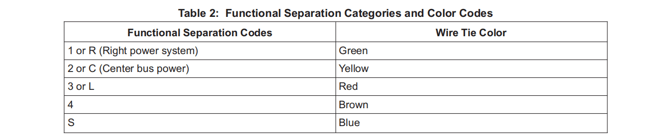
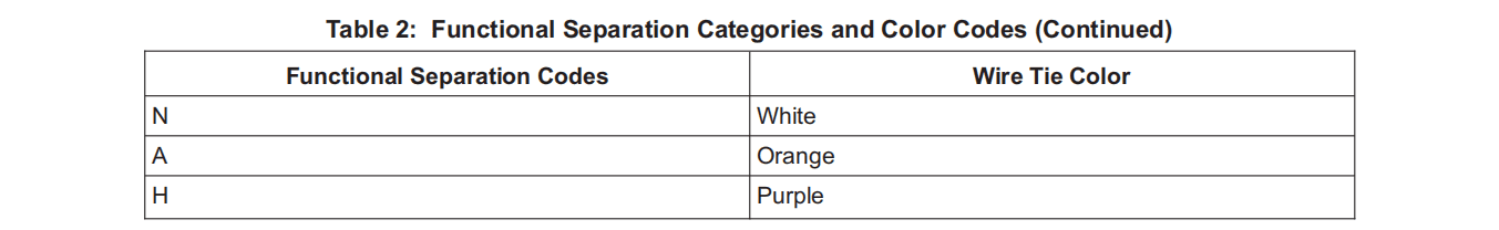
F. When you tie or replace ties on wiring harnesses, use the same type and color as the original, or as shown by the schematic diagram or applicable overhaul instructions. The color of the ties is important because it identifies the wire bundle by separation category, to keep wire bundles of one system apart from those of a different system. Table 2 shows typical Functional Separation Codes which are noted on schematic diagrams, along with the necessary wire tie color. Wires of different codes must have a minimum of 1/4-inch separation. Wires of different subcategory codes must also have a different routing. Thus category L2A wires must have a different routing than category L2B wires, although the two wires have the same red wire ties. Wires with N (neutral) codes can have the same routing as any other coded group unless the subcategories are different. Sleeving can be used to keep the wire bundles at the necessary separation.
绑扎或更换线束上的扎带时,应使用与原装相同的类型和颜色,或按照原理图或适用的大修说明书所示的类型和颜色。扎带的颜色非常重要,因为它可以按分类识别线束,从而将一个系统的线束与不同系统的线束区分开来。表 2 列出了原理图上标注的典型功能分类代码,以及必要的扎线带颜色。不同代码的导线必须至少有 1/4 英寸的间隔。不同子类别代码的导线也必须有不同的走线方式。因此,L2A 类导线的走线必须与 L2B 类导线的走线不同,尽管这两种导线使用相同的红色扎线带。具有 N(中性)代码的导线可以采用与任何其他代码组相同的布线方式,除非子类别不同。可使用套管将线束保持必要的间距。
G. Remove dust, dirt, and other unwanted material from the unit with low-pressure air suction.
用低压空气吸尘器清除设备上的灰尘、污垢和其他不需要的物质。
WARNING :WHEN YOU USE ISOPROPYL ALCOHOL OR ALIPHATIC NAPHTHA, TRY NOT TO BREATHE THE VAPORS TOO MUCH. USE THESE CLEANERS ONLY WITH A GOOD FLOW OF AIR. DO NOT GET THESE CLEANERS IN THE EYES, ON THE SKIN OR CLOTHING. KEEP THESE CLEANERS AWAY FROM HEAT, SPARKS, OR OPEN FLAME.
警告 :使用异丙醇或脂肪族石脑油时,尽量不要吸入过多的蒸汽。仅在空气流通的情况下使用这些清洁剂。不要让这些清洁剂进入眼睛、皮肤或衣物。请将这些清洁剂放在远离热源、火花或明火的地方。
CAUTION :USE ONLY THESE CLEANERS. OTHER CLEANERS COULD DAMAGE ASSEMBLY SURFACES OR CAUSE CIRCUIT FAILURES. ALSO, ISOPROPYL ALCOHOL DISSOLVES ACRYLIC ENCAPSULANT. REFER TO 20-11-01 FOR DETAILS.
注意 :只能使用这些清洁剂。其他清洁剂可能会损坏组件表面或导致电路故障。此外,异丙醇会溶解丙烯酸封装剂。详情请参阅 20-11-01。
H. Clean interior surfaces and electrical contacts with isopropyl alcohol or aliphatic naphtha. Dry fully with low-pressure air.
用异丙醇或脂肪族石脑油清洁内表面和电气插针。用低压空气充分干燥。


4. ASSEMBLY OF COMPONENTS THAT USE THE MIL-T-81714 TERMINATION SYSTEM 使用 mil-t-81714 终端系统的元件的组装
NOTE: Examples are S213T290 lighted pushbutton switches and S231T300 annunciator light indicators.
注:例如 S213T290 照明按钮开关和 S231T300 信号指示灯。
A. Installation of M39029/1-16-20 contacts on one size 20 or 22 AWG wire
在一根 20 或 22 号 AWG 导线上安装 M39029/1-16-20 插针
(1) Remove 3/16 ±1/32 inch of insulation from the end of the wire.
从导线末端去除 3/16 ±1/32 英寸的绝缘层。
(2) Use the applicable crimp tool from Table 3.
使用表 3 中适用的压接工具。
(3) Put the bare end of the wire into the contact crimp barrel, until you can see the conductor through the inspection hole.
将导线的裸露端放入插针压接筒中,直到可以通过检查孔看到导体。
(4) Put the contact in the crimp tool locator to the bottom. Close the tool handle until the ratchet releases and the tool handles open.
将插针放在压接工具定位器的底部。关闭工具手柄,直到棘轮松开,工具手柄打开。
(5) Remove the completed contact-wire assembly from the tool.
从工具中取出已完成的插针-导线组件。
B. Installation of M39029/1-16-20 contacts on two size 24 AWG wires
在两根 24 号 AWG 导线上安装 M39029/1-16-20 插针
(1) Remove 3/16 ±1/32 inch of insulation from the end of each wire.
从每根导线的末端去除 3/16 ±1/32 英寸的绝缘层。
(2) Use the applicable crimp tool from Table 3.
使用表 3 中适用的压接工具。
(3) Put the bare end of the wire into the contact crimp barrel, until you can see the conductor through the inspection hole.
将导线的裸端放入插针压接筒中,直到可以通过检查孔看到导体。
(4) Put the contact in the crimp tool locator to the bottom. Close the tool handle until the ratchet releases and the tool handles open.
将插针放在压接工具定位器的底部。关闭工具手柄,直到棘轮松开,工具手柄打开。
(5) Remove the completed contact-wire assembly from the tool.
从工具中取出已完成的插针-导线组件。
C. Installation of contacts
安装插针
(1) Use the applicable insertion tool per Table 4.
按照表 4 使用适用的插入工具。
(2) Put the contact into the insertion tool tip. Put the contact carefully through the grommet hole and push lightly until the contact is fully engaged.
将插针插入插入工具尖端。小心地将插针穿过索眼孔,然后轻轻推动,直至插针完全啮合。
(3) Pull lightly on the wire to make sure the contact is correctly engaged. Do not make a nick in the wire insulation with your fingernails.
轻轻拉动导线,确保插针正确接合。不要用指甲在导线绝缘层上划出缺口。
D. Removal of contact
拆卸插针
(1) Use the applicable removal tool from Table 4.
使用表 4 中适用的拆卸工具。
(2) Put the wire into the back part of the tool, then put the wire into the front portion of tool.
将导线放入工具的后部,然后将导线放入工具的前部。
(3) Hold the wire and removal tool together and remove them as a unit from the insert cavity.
将导线和拆卸工具握在一起,将它们作为一个整体从插入腔中取出。


5. S231T290 SWITCH REPAIRS 修理 S231T290 开关
CAUTION :REMOVE POWER FROM THE MODULE BEFORE YOU REMOVE THE CAP.
注意 :卸下盖帽之前,请先断开模块电源。
NOTE: See Figure 3 for S231T290-1000, -4000 series and Figure 4 for S231T290-2000, -3000, -5000 series switches.
注:S231T290-1000、-4000 系列开关参见图 3,S231T290-2000、-3000、-5000 系列开关参见图 4。
A. Removal of S231T290 switches from the instrument panel.
从仪表板上拆下 S231T290 开关。
(1) Disconnect the wiring before you start to remove the switch from the panel.
在开始从面板上拆卸开关之前,先断开接线。
(2) Remove the sleeve from the base (housing) assembly.
从底座(外壳)组件上拆下套管。
(a) S231T290-2000, -3000, -5000 series — Remove the two screws on the end of the switch.
S231T290-2000、-3000、-5000 系列 — 卸下开关末端的两个螺钉。
(b) S231T290-1000, -4000 series — Pull off the cap assembly to get at the mounting screws on the master module. Then turn the mounting screws counterclockwise eight turns.
S231T290-1000、-4000 系列 — 将盖帽组件拉出,取下主模块上的安装螺钉。然后将安装螺钉逆时针旋转八圈。
(3) Slide the sleeve off the switch. Remove the switch from the panel.
将套管从开关上滑下。从面板上取下开关。
B. Cap assembly
盖帽组件
(1) Remove the cap assembly to replace lamps and to replace the fuse/diode module. Removal of the cap assembly is not necessary to install the switch guard.
拆卸盖帽组件以更换灯管和保险丝/二极管模块。安装开关防护罩时不需要拆下盖帽组件。
(2) Make sure that the cap assembly is in the up position before you try to remove it. You cannot remove the cap when it is in the depressed position.
在尝试取下盖帽组件之前,请确保盖帽组件处于向上位置。盖帽处于凹陷位置时无法取下。
(3) On S231T290-2000 series switches, push the cap assembly down 0.065-0.165 inch. On all switches, pull the cap out with your fingertips (do not use a tool). The cap will come out approximately 1 inch before it is held by two wire retaining clips.
在 S231T290-2000 系列开关上,将盖帽组件向下推入 0.065-0.165 英寸。在所有开关上,用指尖将盖帽拉出(不要使用工具)。在帽盖被两个导线固定夹夹住之前,帽盖会脱出约 1 英寸。
(4) Repair of S231T290 lens cap assembly
修理 S231T290 镜头盖组件
(a) Remove the two tabs from the lens assembly. Sand the cut edges smooth.
取下镜头组件上的两个卡舌。将切边打磨光滑。
(b) Remove loose dust with an air blast. Clean the inside edges of the lens assembly and the mating area of the lens capsule assembly with isopropyl alcohol.
用气枪清除松散的灰尘。用异丙醇清洁镜头组件的内边缘和镜头盖组件的接合区域。
(c) Assemble the lens assembly and the lens capsule assembly. Back off the lens assembly to make a gap approximately 0.050 inch wide, and fill this gap on all four sides with Loctite Superbonder Adhesive No. 416.
组装透镜组件和透镜座组件。后退透镜组件,使其形成约 0.050 英寸宽的间隙,并用乐泰 Superbonder 416 号粘合剂填满四边的间隙。
(d) Push the lens and the lens capsule together with finger pressure only. Remove unwanted adhesive. Hold the finger pressure for 15 seconds.
仅用手指压力将透镜和透镜座推到一起。去除不需要的粘合剂。保持手指压力 15 秒钟。
(e) Let the unit cure overnight at room temperature.
让其在室温下固化一夜。
C. Lamp Replacement
更换灯泡
(1) Turn the cap 90 degrees in one direction or the other to expose the bases of the lamps. With fingernails, pull out lamps to be replaced. Install the replacement lamps in the empty lamp sockets.
向一个方向或另一个方向旋转盖子 90 度,露出灯管的底座。用指甲拔出要更换的灯管。将替换的灯管安装到空的灯管插座中。
(2) Turn the cap back to the correct position.
将盖子转回正确位置。
D. Fuse/Diode Module Replacement
保险丝/二极管模块更换
(1) S231T290-1000, -4000 series:
S231T290-1000、-4000 系列:
(a) Pull the lens cap out from the master module. Turn the lens on the bail wires to get at the mounting screws. Turn the mounting screws counterclockwise eight turns.
从主模块上拉出镜头盖。转动保线上的透镜以接触到安装螺钉。逆时针旋转安装螺钉八圈。
(b) To remove the master module, turn the lens cap 90 degrees, put a finger between the bail wires, and pull on the lens cap as you hold the housing assembly in position. If the bail wires come off the master module before the master module comes out, remove the master module with insulated needle nose pliers.
要卸下主模块,将镜头盖旋转 90 度,将手指放在保线之间,然后拉住镜头盖,同时将外壳组件固定在原位。如果在主模块出来之前,保压线已从主模块上脱落,则用绝缘尖嘴钳取下主模块。
(c) Turn the assembly to put the fuse/diode card in the up position. Pull the fuse/diode card straight back to disconnect it from the master module.
转动组件,将保险丝/二极管卡置于向上位置。将保险丝/二极管卡直接向后拉,使其与主模块断开。
(d) Hold the replacement fuse/diode card between your fingers and plug the card into the socket pins of the master module.
用手指夹住更换的保险丝/二极管卡,将其插入主模块的插座针脚。
(2) S231T290-2000, -3000, -5000 series:
S231T290-2000、-3000、-5000 系列:
NOTE: Some switch assemblies may contain two fuse/diode modules (Figure 4).
注:某些开关组件可能包含两个保险丝 / 二极管模块 (图 4)。
(a) The cap assembly must be completely removed from the base assembly. Disengage the wire retaining clips from the holes in the corners of the cap assembly.
必须将盖帽组件从底座组件上完全拆下。将电线固定夹从帽组件四角的孔中分离出来。
(b) Hold the fuse/diode module with padded needle nose pliers and pull out. The fuse/diode module will slide straight out of the base.
用带盘的尖嘴钳夹住保险丝/二极管模块并拉出。保险丝/二极管模块将从底座中直接滑出。
(c) Hold the replacement module with the pliers and push it into the empty socket, with the notch of the module to the back and the center of the switch. If the notch is not in the correct position, the module will not go in easily, or it will cause the cap assembly to lock in the UP position after assembly.
用钳子夹住替换模块,将其推入空插座中,使模块的凹口朝向开关的背面和中心。如果凹口位置不正确,模块将不容易装入,或在组装后导致盖帽组件锁定在 UP 位置。
E. Installation of the Cap Assembly
安装盖帽组件
(1) On S231T290-2000, -3000, -5000 series only, align the small keying pin on the center shaft of the cap with the keying slot inside the cavity of the base assembly (master module).
仅在 S231T290-2000、-3000、-5000 系列上,将盖帽中心轴上的小键销与基座组件 (主模块)腔内的键槽对齐。
(2) Install the wire retaining clips if you removed them.
如果已取下电线固定夹,则将其安装上。
(a) S231T290-1000, -4000 series — Install the hooked ends of the clips into the correct clip slots of the master module assembly.
S231T290-1000、-4000 系列 — 将夹子的钩端安装到主模块组件的正确夹槽中。
(b) S231T290-2000, -3000, -5000 series — Install the clip ends into the correct holes in the corners of the cap assembly.
S231T290-2000、-3000、-5000 系列 — 将夹子两端安装到帽组件角上的正确孔中。
CAUTION :MAKE SURE THAT THE WIRE FOLLOWER STAYS IN THE CAM TRACK WHEN THE CAM PLATE IS MOVED BACK AND FORTH.
注意:前后移动凸轮板时,确保从动件始终位于凸轮轨道内。
(3) S231T290-1000, -4000 series only — Temporarily turn the cap assembly 90 degrees to let you get at the master module. Push the master module into the housing assembly and make sure that the metal contacts on the rear of the diode/fuse card align with the mating receptacle contacts in the connector block (Figure 3). Put the complete switch assembly back into the instrument panel before you replace the cap assembly. Move the mounting sleeve over the housing assembly, with the mounting lug holes aligned. Tighten the mounting screws until snug. See that the mounting lugs engage the mounting sleeve. With a jeweler’s screwdriver, alternately tighten the mounting screws in 1/4-turn increments until both screws are tightened to 15-20 ounce-inches. Then turn the lens cap assembly back to be correctly aligned with the master module.
仅限 S231T290-1000、-4000 系列 — 暂时将盖帽组件旋转 90 度,以便接触主模块。将主模块推入外壳组件,确保二极管/保险丝卡背面的金属插针与连接器组中的配对插座插针对齐(图 3)。在更换盖帽组件之前,将整个开关组件放回仪表板。将安装套管移到外壳组件上,对准安装耳孔。拧紧安装螺钉直至拧紧。查看安装耳是否与安装套管啮合。使用螺丝刀,以 1/4 圈的增量交替拧紧安装螺钉,直到两个螺钉都拧紧到 15-20 盎司英寸。然后将镜头盖组件转回,使其与主模块正确对齐。
(4) Align the center shaft of the cap assembly with the guide hole in the center of the base assembly (master module). Lightly press the cap assembly with your thumb until it latches. Make sure the cap is square with the base (housing) assembly to prevent damage to the guide ring. Push and release the switch a few times to see that it operates correctly.
将镜头盖组件的中心轴与底座组件(主模块)中心的导向孔对准。用拇指轻压镜头盖组件,直至其锁上。确保盖帽与底座 (外壳)组件保持正对,以防损坏导向环。按下并松开开关几次,确认其操作正常。
F. Installation of S231T290 switches in the instrument panel.
在仪表板上安装 S231T290 开关。
(1) Put the switch unit in the panel cutout.
将开关放入面板开孔中。
(2) Install the sleeve.
安装套管。
CAUTION :DO NOT TIGHTEN THE SCREWS MORE WHEN YOU FEEL RESISTANCE. A GAP BETWEEN THE BACK OF THE SWITCH AND THE TABS ON THE SLEEVE IS PERMITTED.
注意 :当感到有阻力时,不要再拧紧螺钉。开关背面与套筒上的卡口之间允许有间隙。
(a) S231T290-2000, -3000, -5000 series — Install the sleeve and the two screws. Tighten the screws to 18-22 ounce-inches.
S231T290-2000、-3000、-5000 系列 — 安装套管和两个螺钉。将螺钉拧紧至 18-22 盎司英寸。


6. S231T300 ANNUNCIATOR REPAIRS / S231T300 信号器修理
A. Removal (Figure 5)
拆卸(图 5)
(1) Disconnect wires with the extraction tool (Table 4).
用拔出工具(表 4)断开电线。
(2) Pull out on the lens cap assembly as for lamp replacement.
像更换灯泡一样拉出镜头盖组件。
(3) Hold the top and the bottom of the diode/fuse card with your thumb and forefinger as shown. Pull the card assembly straight out until the back of the card is clear of the base assembly. Push up on the card and remove it.
如图所示,用拇指和食指握住二极管/保险丝卡的顶部和底部。将卡组件直接拉出,直到卡的背面脱离底座组件。向上推卡并将其取出。
(4) Lightly squeeze the sides of the drawer assembly and remove it from the base assembly.
轻轻挤压抽屉组件的两侧,将其从底座组件中取出。
(5) Put a small screwdriver into the base assembly as shown and loosen the screws until the mounting lugs turn into the housing and the sleeve comes loose. Remove the sleeve from the indicator assembly. Remove the indicator assembly from the panel cutout.
如图所示,将一把小螺丝刀插入底座组件,拧松螺丝,直到安装耳转入外壳,套管松开。从指示灯组件上取下套筒。从面板开口处取下指示灯组件。
B. Lamp Replacement
更换灯泡
(1) Hold the sides of the lens cap between your thumb and forefinger. Pull out as you rock it slightly side-to-side, until the lens cap comes loose. It will release suddenly and must not be permitted to hit against the slide mechanism stops at the fully extended position.
用拇指和食指夹住镜头盖的两侧。一边向两侧轻微摇晃一边向外拉,直到镜头盖松开。镜头盖会突然松开,在完全伸展的位置,切勿让镜头盖碰到滑动机构的止挡块。
(2) Turn the lens cap assembly downward to get at the lamp bases. Remove and replace lamps as necessary. There are flats on the metal lamp holder sleeves. Turn the sleeve to align the flat side with the raised shoulder on the cap assembly. Push the lamps in until fully down against the sleeve. Push and release the lamp bases against the springs. Replace the cap assembly if it catches.
向下转动镜头盖组件,以接触灯座。根据需要拆卸和更换灯泡。金属灯座套筒上有平面。转动套筒,使平面对准镜头盖组件上的凸肩。将灯管推入,直到完全靠在套筒上。将灯座推到弹簧上,然后松开。如果帽盖组件卡住,请更换。
(3) Turn the lens cap assembly back up to align it with the drawer assembly, and then move it into the base. Push on the lens cap until you feel a click.
将镜头盖组件向上翻转,使其与抽屉组件对齐,然后将其移入底座。按下镜头盖,直到感觉到咔嗒一声。
C. Installation
安装
(1) Make sure the assembly is disassembled as for removal.
确保组件已按拆卸步骤拆卸。
(2) Install the base assembly into the panel cutout. TOP is printed on the base assembly housing.
将底座组件安装到面板开孔中。TOP 印在底座组件外壳上。
CAUTION :MAKE SURE THE MOUNTING SLEEVE IS TURNED TO THE CORRECT POSITION, OR IT WILL PREVENT INSTALLATION, AND COULD PUT THE PINS OUT OF ALIGNMENT WHEN THE SCREWS ARE TIGHTENED.
注意 :确保安装套筒转到正确位置,否则会妨碍安装,并可能在拧紧螺钉时使插销不对齐。
(3) Slide the mounting sleeve over the rear of the base assembly. The solid bars between the sleeve ends must align with the mounting screws. If an open space is aligned with the mounting screws, turn the sleeve end-for-end.
将安装套管滑入底座组件的后部。套筒两端之间的实心杆必须与安装螺钉对齐。如果出现与安装螺钉对齐的空隙,请将套管端对端旋转。
CAUTION :DO NOT TIGHTEN THE MOUNTING SCREWS TOO MUCH, OR YOU COULD PUT THE CONTACTS OUT OF ALIGNMENT.
注意 :不要将安装螺钉拧得太紧,否则会导致插针不对齐。
(4) Carefully turn the mounting screws until the mounting lugs turn and fully engage the mounting sleeve. Do not tighten. See that both mounting lugs are engaged, and that the sleeve is centered over the panel cutout. Alternately tighten the screws to 12 ounce-inches maximum.
小心转动安装螺钉,直至安装耳转动并完全啮合安装套管。不要拧紧。确保两个安装耳均已啮合,且套管位于面板开口的中心位置。交替拧紧螺钉,最大拧紧力为 12 盎司-英寸。
(5) Lightly squeeze the sides of the drawer assembly and install it in the housing. Install the diode/fuse card assembly, rear end first, and lightly squeeze the front end down until the card pops into place. Make sure the 3-pronged end of the card is nearest to the lamps. Do not squeeze the sides of the drawer assembly while you push down on the card.
轻轻挤压抽屉组件的两侧,将其安装到外壳中。先安装二极管/保险丝卡组件的后端,然后轻轻向下挤压前端,直到卡弹出到位。确保卡的三叉端离灯泡最近。向下挤压插卡时,不要挤压抽屉组件的两侧。
(6) Turn the lens cap assembly upward to align with the drawer assembly and slide into the base. Push down on the lens cap until you feel a click.
向上转动镜头盖组件,使其与抽屉组件对齐并滑入底座。向下按镜头盖,直到感觉到卡嗒声。
(7) Install wiring with the applicable insertion tool (Table 4).
使用适用的插入工具安装导线(表 4)。


7. LIGHTPLATES 灯盘
A. Cleaning
清洁
(1) Brush off dust and dirt with a non-metallic soft bristle brush.
用非金属软毛刷刷去灰尘和污垢。
CAUTION:DO NOT WIPE LENS SURFACES WITH ABRASIVE MATERIALS OR CLEANERS. YOU COULD SCRATCH THE COATING ON THE LENS.
注意:不要用研磨材料或清洁剂擦拭镜头表面。否则会刮伤镜片上的涂层。
(2) Wipe the surfaces with a soft cloth wet with isopropyl alcohol.
用异丙醇浸湿的软布擦拭表面。
(3) Dry the cleaned surfaces with a soft, clean cloth.
用干净的软布擦干清洁过的表面。
B. Examine the lightplate for cracks, scratches, worn-off or damaged markings, or other defects.
检查灯盘是否有裂缝、划痕、磨损或损坏的标记或其他缺陷。
C. Lens Replacement
更换透镜
(1) Remove the lens. These are bonded in position with sealant.
取出透镜。这些透镜是用密封胶粘合的。
(2) Remove unwanted sealant from the window opening. Clean the area with isopropyl alcohol.
去除窗口开口处多余的密封胶。用异丙醇清洁该区域。
(3) With a cotton swab, apply a thin layer of RTV primer to the surfaces of the window opening which will touch the lens. Let the primer dry 2 hours.
用棉签在窗口开口与透镜接触的表面涂上一层薄薄的 RTV 底漆。让底漆干燥 2 小时。
(4) Apply a thin bead of RTV sealant around the edge of the window opening.
在窗口开口边缘涂上一层薄薄的 RTV 密封胶。
(5) Carefully install the replacement lens into the window opening. Push the lens down lightly on all four corners. Do not push the sealant out of the front of the panel.
小心地将替换透镜安装到窗户开口中。将透镜的四个角轻轻向下推。不要将密封胶挤出面板前部。
(6) Apply more sealant around the edge of the lens. Make the sealant surface smooth with the lens face, and remove sealant that gets on the front of the lightplate.
在透镜边缘涂抹更多密封胶。使密封胶表面与透镜面平滑,并清除沾到灯板前面的密封胶。
(7) Put the lightplate face down on a clean surface. Let the sealant cure for 24 hours.
将灯盘正面朝下放在干净的表面上。让密封剂固化 24 小时。
(8) After the cure is completed, apply four pounds pressure to each corner of the lens. Examine the lens to make sure it stays sealed from water.
固化完成后,对透镜的每个角施加四磅重的压力。检查透镜,确保其不进水。
D. Light Bulb Replacement
更换灯泡
(1) Put the lightplate assembly face down on a cloth or plastic sheet.
将灯盘组件面朝下放在布或塑料布上。
(2) Remove the screws from the rear of the lightplate.
取下灯盘后部的螺钉。
(3) Remove as a unit the backplate and the circuit board subassembly from the lightplate. Then disassemble the backplate from the circuit board to get at the solder connections.
将背板和电路板组件作为一个整体从灯盘上拆下。然后从电路板上拆下背板,以查看焊接连接。
(4) With a 600°F soldering iron, unsolder the defective light bulb.
用 600°F 的烙铁拆焊故障灯泡。
(5) Install a replacement light bulb. Many lightplates have printed data on them which can help identify replacement light bulbs and other parts. Most lightplates use 5-volt, 0.06-amp unbased lamps, such as part number 50001 available from Avio Corp. (V9U239) or Wamco (V58774). Solder the leads and cut off the unwanted lead lengths.
安装一个替换灯泡。许多灯盘上都印有数据,有助于识别替换灯泡和其他零件。大多数灯盘使用 5 伏、0.06 安培的无基座灯,如 Avio Corp. (V9U239) 或 Wamco (V58774) 提供的件号 50001。焊接引线并剪掉不需要的引线长度。
(6) Put the circuit board on the lightplate. Make sure there is clearance between the replacement light bulb and the lightplate. Unsolder and adjust the location of the replacement light bulb as necessary.
将电路板放在灯盘上。确保替换灯泡与灯板之间有间隙。必要时拆焊并调整替换灯泡的位置。
(7) Remove the circuit board from the lightplate. Repair the encapsulant as necessary per SOPM 20-11-01.
从灯盘上拆下电路板。必要时按照 SOPM 20-11-01 修理封装。
(8) With the lightplate face down on a cloth or plastic sheet, install the circuit board and the backplate with the screws.
将灯盘朝下放在布或塑料布上,用螺丝安装电路板和背板。
(9) After the light bulb replacement is complete and the lightplate is back together, we recommend you make a check of the lightplate to see if it is serviceable, with the correct rated voltage applied to the power connector at the rear of the unit.
在灯泡更换完成和灯盘组装完毕后,我们建议您将正确的额定电压施加到部件后部的电源连接器上,检查灯盘是否可以使用。
E. Power Connector Replacement
更换电源连接器
(1) Put the lightplate assembly face down on a cloth or plastic sheet.
将灯盘组件面朝下放在布或塑料布上。
(2) Remove the screws from the rear of the lightplate.
取下灯盘后部的螺钉。
(3) Remove as a unit the backplate and the circuit board subassembly from the lightplate. Then disassemble the backplate from the circuit board to get at the solder connections.
将背板和电路板组件作为一个整体从灯盘上拆下。然后从电路板上拆下背板,以查看焊接连接。
(4) With a 600°F soldering iron, unsolder the four tabs and the center section of the defective power connector. Bend the four tabs up to release the connector.
使用 600°F 的烙铁,拆焊故障电源连接器的四个接片和中间部分。将四个卡舌向上弯曲,松开连接器。
(5) Install a replacement power connector. Most lightplates use part number S005002 available from Aviocorp (V9U239). Other lightplates use part number 800000119 available from IDD Aerospace Corp. (V05617), which mates with the 800000121-1 power connector on most panels. Bend the four tabs down against the circuit board. Then solder the tabs and the center section.
安装替换电源连接器。大多数灯盘使用 Aviocorp (V9U239) 提供的件号 S005002。其他灯盘使用 IDD Aerospace Corp. (V05617) 提供的件号 800000119,该零件与大多数面板上的 800000121-1 电源连接器配合使用。将四个接片向下弯曲,抵住电路板。然后焊接接片和中心部分。
(6) Put the circuit board on the lightplate.
将电路板放在灯盘上。
(7) With the lightplate face down on a cloth or plastic sheet, install the circuit board and the backplate with the screws.
将灯板面朝下放在布或塑料板上,用螺钉安装电路板和背板。
(8) After the power connector replacement is complete and the lightplate is back together, we recommend you make a check of the lightplate to see if it is serviceable, with the correct rated voltage applied to the power connector at the rear of the unit.
在完成电源连接器的更换并重新组装好灯盘后,我们建议您将正确的额定电压施加到部件后部的电源连接器上,检查灯盘是否可以使用。
F. Painted Markings
涂漆标记
(1) Touch up the painted markings with the applicable paint system shown in Table 5.
使用表 5 所示的适用油漆系统修补油漆标记。

G. Captive Fasteners
拴式紧固件
(1) See Figure 6 for applicable fasteners by lightplate color and hole size.
有关适用的紧固件,请按灯板颜色和孔尺寸参见图 6。
